
Adjustable removable restraining stop for double hung windows
a technology for restraining stops and double hung windows, which is applied in the direction of latching locks, wing accessories, carpet fasteners, etc., can solve the problems of not being able to allow such modifications, and achieve the effect of convenient grip and positive locking feel
- Summary
- Abstract
- Description
- Claims
- Application Information
AI Technical Summary
Benefits of technology
Problems solved by technology
Method used
Image

Examples
Embodiment Construction
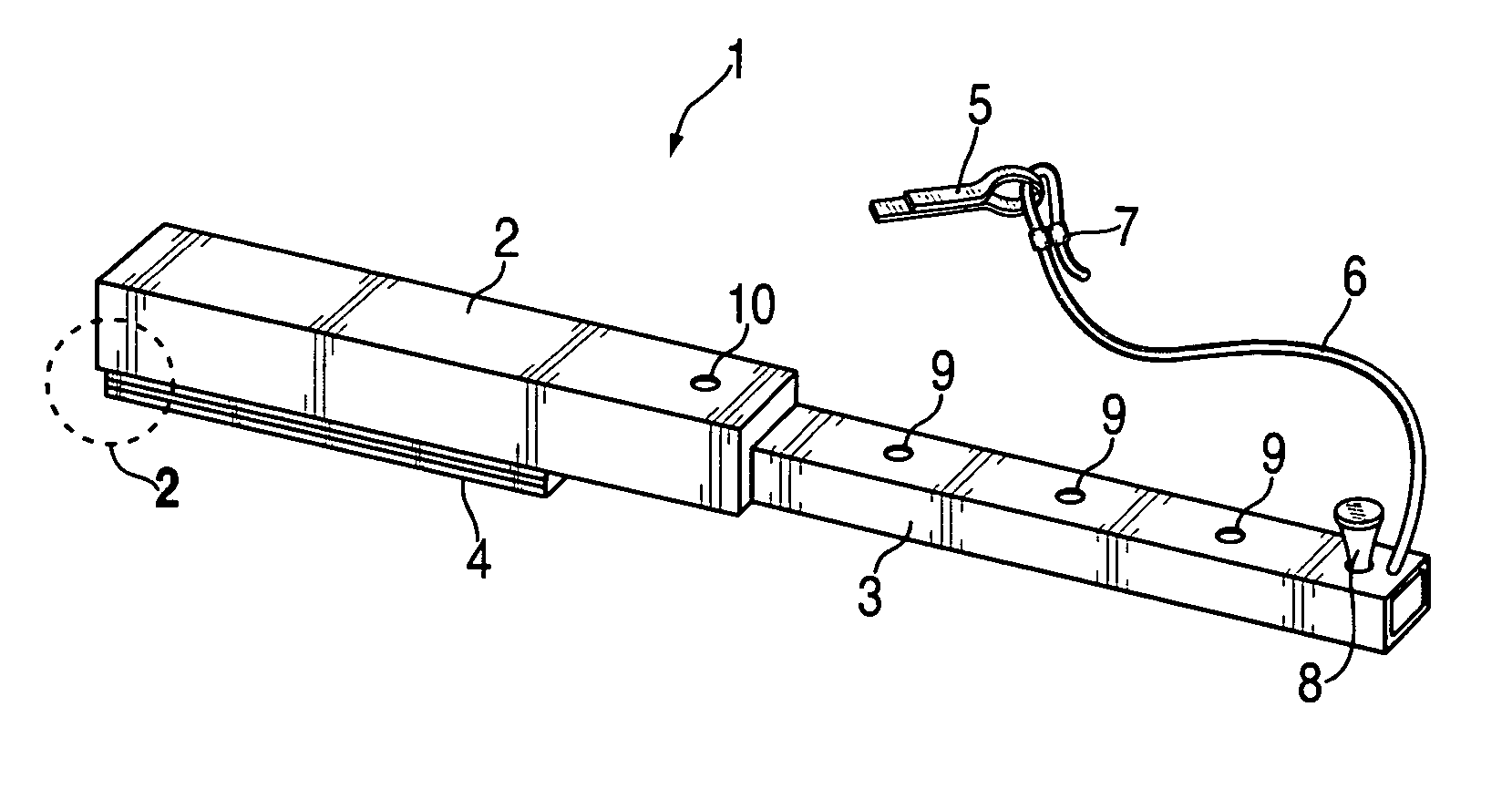
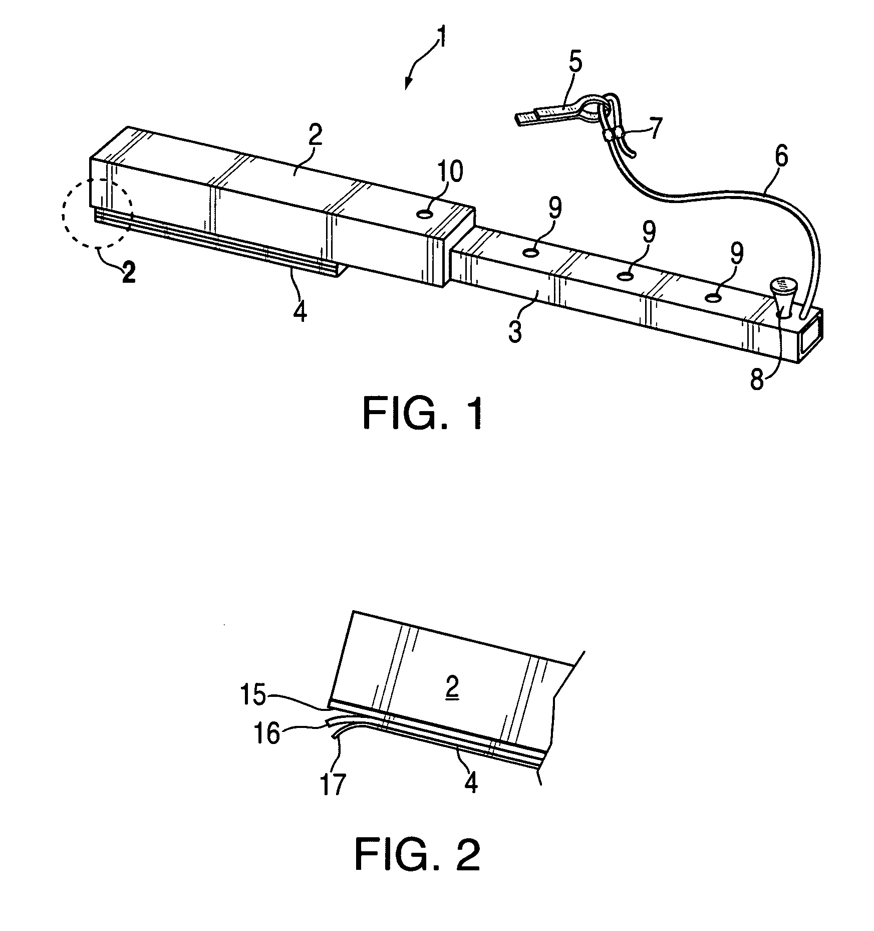
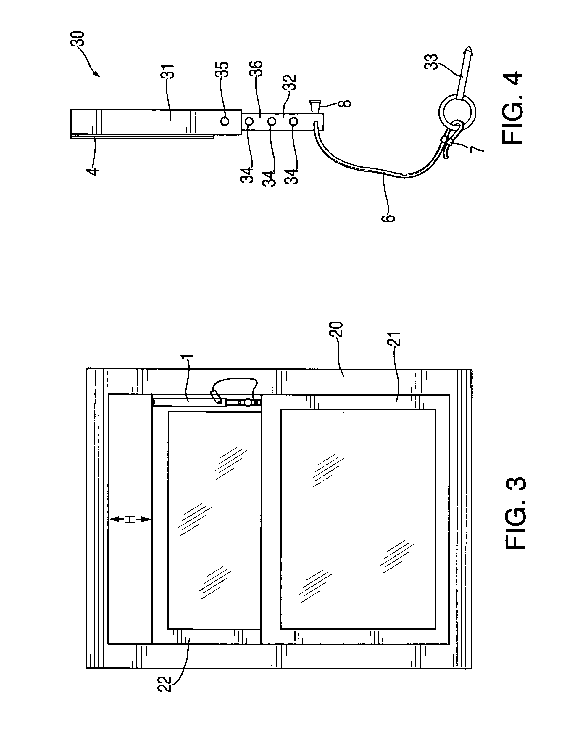
[0016]FIG. 1 shows adjustable restraining stop assembly 1 with outer tube 2, inner tube 3, and mounting hook and loop layer 4. A convenience knob 8 is attached near the distal end of inner tube 3. Adjustment is set by placing one of holes 9 on the front surface of inner tube 3 in registration with hole 10 on tube 2 and then inserting cotter pin 5 through hole 10 and into the desired hole 9 thereby locking the two tubes together. A lanyard line 6 is used to prevent losing cotter pin 5; it is retained in cotter pin 5 by using compression sleeve 7 to form a loop splice. FIG. 2 shows the various layers of the hook and loop layer 4. As supplied by the factory, the loop layer 15 is already bonded to tube 2. Layers 16 and 17, the hook layer and its release liner respectively, are also attached. To attach the assembly to the sash frame, the user must only remove release liner 17 exposing the layer of pressure sensitive adhesive and then just press assembly 1 against the window sash frame as...
PUM
 Abstract
Description
Claims
Application Information