Driving device

a technology of driving device and gearing, which is applied in the direction of dynamo-electric machines, synchronous motor starters, toothed gearings, etc., can solve the problems of high current in the feed line and the other electrical and electronic equipment in the motor vehicl

Active Publication Date: 2012-08-07
STABILUS
View PDF18 Cites 9 Cited by
  • Summary
  • Abstract
  • Description
  • Claims
  • Application Information

AI Technical Summary

Benefits of technology

[0006]It is an object of the invention to provide a driving device of the type mentioned above which prevents EMC loads of this kind particularly in the initial range of the outward stroke of the driving device.
[0009]Further, the power supply can include an electric energy storage arranged in the housing tube and / or by an electric voltage amplifier (booster). As a result, the energy storage is switched on in the initial range of the outward stroke and provides temporary high power. Voltage is likewise made available to the electric motor by the electric voltage amplifier by way of the vehicle power supply, which ensures a higher starting torque of the electric motor drive arranged downstream.
[0010]Accordingly, the structural dimensions of the driving device can also be kept small through the use of a low-power, compact electric motor drive. However, the electric motor drive can be loaded beyond its nominal rating for short periods of time without being damaged. Blocking currents occurring at the start of the outward stroke are compensated simultaneously and do not lead to a significant loading of the vehicle power supply. There is also a compensation of voltage losses in the feed lines.
[0012]When the power output stage and / or the electric voltage amplifier and / or the electric energy storage are / is arranged in series with the electric motor drive, this results in a compact construction and, therefore, small structural dimensions of the driving device.
[0015]To achieve a temporary increase in power of the electric motor drive, the electromotor voltage amplifier can be a DC-DC converter, a diode cascade or a transformer. The diode cascade has the advantage that it generates only low switching losses and can be implemented in a small space.

Problems solved by technology

High actuating forces are required particularly in the initial range of the outward stroke which lead to high currents in the feed line.
These high currents generate a substantial EMC load which, particularly when the driving device is used in motor vehicles, can lead to problems in the other electrical and electronic equipment in the motor vehicle.

Method used


Image

  • Driving device
  • Driving device
  • Driving device

Examples


Embodiment Construction

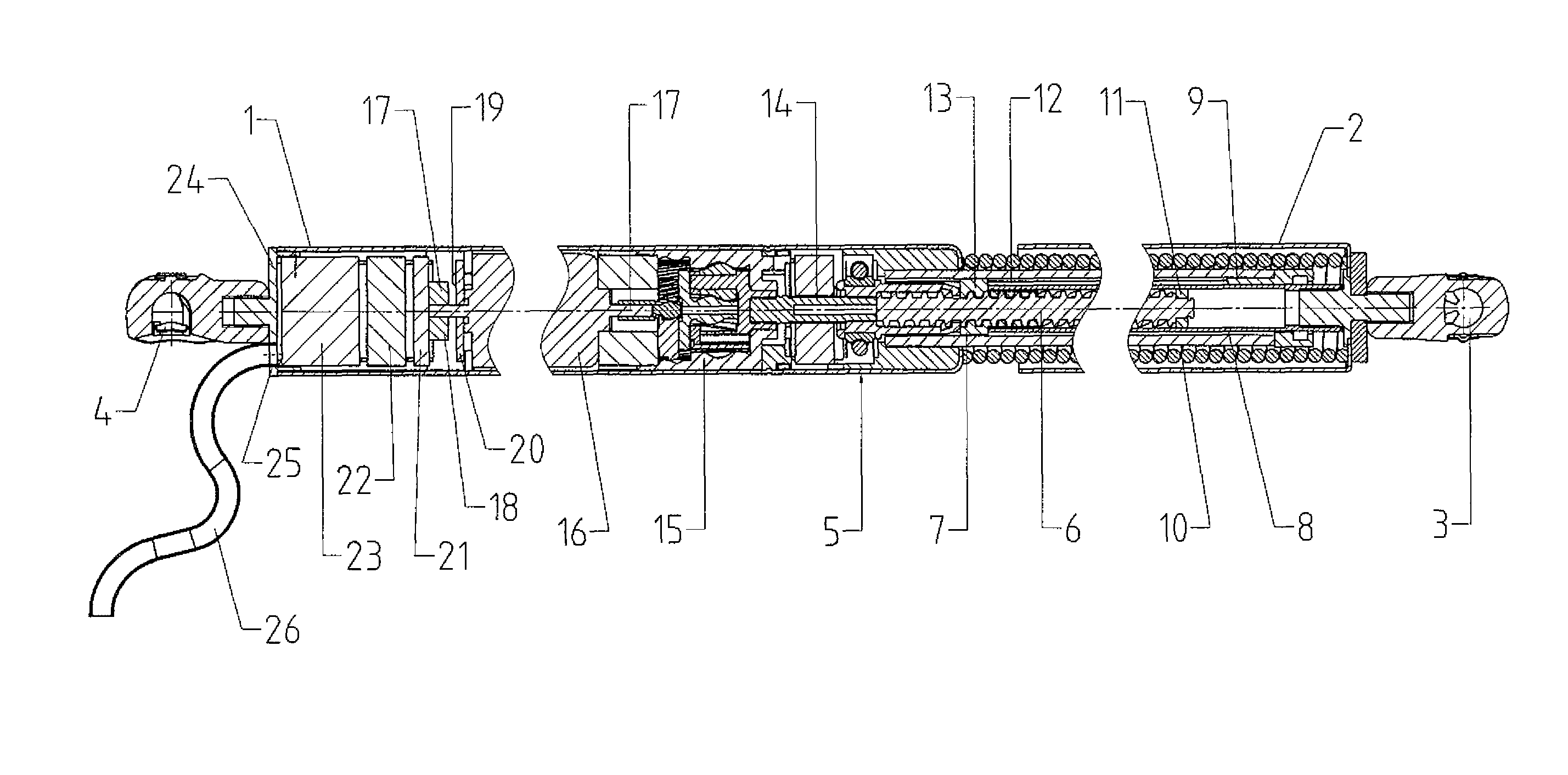
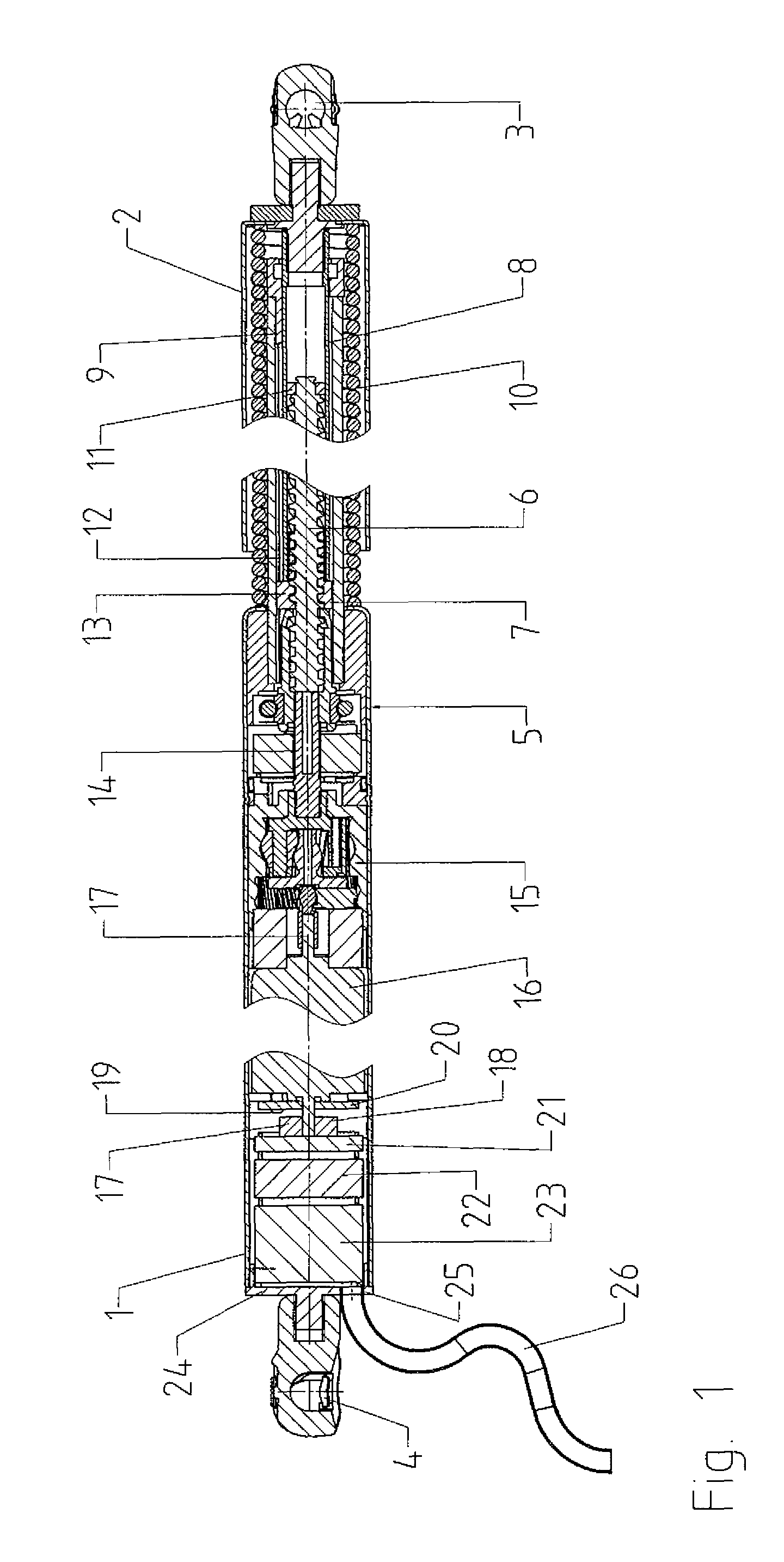
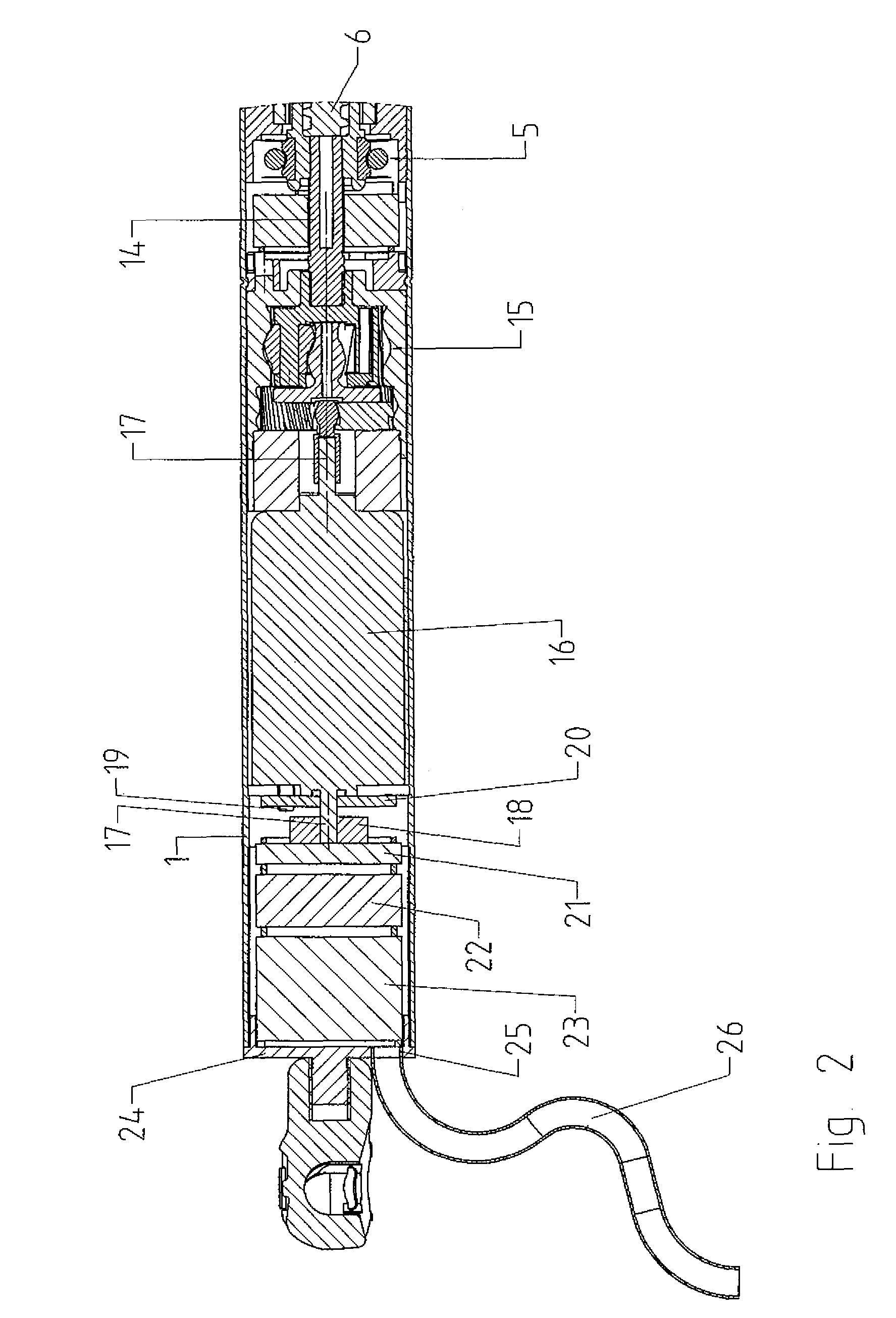
[0022]The driving device shown in the drawings has a housing tube 1 at which an outer tube 2 is guided so as to be displaceable in a telescoping manner.

[0023]A first ball socket 3 is arranged at the end of the outer tube 2 located opposite to the housing tube 1, and a second ball socket 4 is arranged at the end of the housing tube 1 located opposite to the outer tube 2. The driving device can be connected in an articulated manner to a stationary structural component part of the body of a motor vehicle and to a movable structural component part of the motor vehicle constructed as a hatch by means of the first and second ball sockets 3 and 4.

[0024]A bearing 5 is fixedly installed in the end area of the housing tube facing the outer tube 2, one end of a threaded spindle 6 projecting coaxially into the outer tube 2 being rotatably supported at this bearing 5. The threaded spindle 6 is supported axially by means of the bearing 5.

[0025]A spindle nut 7 is arranged on the threaded spindle 6...


PUM


Abstract

A device for moving a movable structural component with respect to a stationary structural component includes a first fastening element which can be fastened to the movable structural component, and a housing tube having a second fastening element which can be fastened to the stationary structural component. A spindle drive for moving the first fastening element axially relative to the housing between an extended position and a retracted position includes a spindle nut arranged on a threaded spindle. An electric motor arranged in the housing tube drives one of the spindle nut and the threaded spindle in rotation. A power supply for supplying power to the electric motor includes a power output stage arranged in the housing tube, wherein the power output stage is shielded from electrical and magnetic fields.

Description

BACKGROUND OF THE INVENTION[0001]1. Field of the Invention[0002]The invention is directed to a driving device, particularly for a hatch in a vehicle, with a first fastening element which can be connected to a stationary structural component part or to a movable structural component part, and with a housing tube which is movable axially relative to the first fastening element and can be fastened to the other component part. A spindle drive has a spindle nut arranged on a threaded spindle, by which the first fastening element and the housing tube are drivable so as to be movable axially relative to one another between a moved out position and a moved in position, wherein the spindle drive is rotatably drivable by an electric motor drive which is arranged in the housing tube and which is controllable by a control unit having a power output stage.[0003]2. Description of the Related Art[0004]In a driving device of the type mentioned above, it is known to arrange the control unit at a dis...

Claims


Application Information

Patent Timeline
Patent Type & Authority Patents(United States)
IPC IPC(8): H02K11/00E05F15/10
CPCE05F15/622E05Y2900/548E05Y2800/00Y10T74/18576E05Y2800/238E05Y2800/232
Inventor BOCHEN, MARIANMINTGEN, ROLF
Owner STABILUS
Why Eureka
Try Eureka