Inverter control apparatus

a control apparatus and inverter technology, applied in the direction of electric generator control, dynamo-electric converter control, dynamo-electric gear control, etc., can solve the problems of insufficient starting torque, failure of inverter or motor, failure of inverter, etc., to achieve high starting torque, stable starting, and fast response

Active Publication Date: 2018-09-06
LSIS CO LTD
View PDF2 Cites 1 Cited by
  • Summary
  • Abstract
  • Description
  • Claims
  • Application Information

AI Technical Summary

Benefits of technology

[0007]Therefore, an object of the present disclosure is to provide an inverter control apparatus for stably starting a system requiring high starting torque and fast response when a brake is released by improving an insufficiency of the starting torque due to a voltage drop upon voltage or frequency control.

Problems solved by technology

However, in some systems, V / F control is performed due to costs incurred for maintenance of an encoder.
However, when an inverter is controlled by V / F control, starting torque may be insufficient due to a voltage drop caused by stator resistance and leakage inductance of a motor in a slow driving area in which an output voltage of the inverter is low.
Also, a starting failure due to the insufficiency of the starting torque causes an excessive current, which may cause a failure of the inverter or a failure of the motor.

Method used


Image

  • Inverter control apparatus
  • Inverter control apparatus
  • Inverter control apparatus

Examples


Embodiment Construction

[0021]In order to fully understand configurations and advantageous effects of the present invention, exemplary embodiments of the present invention will be described with reference to the accompanying drawings.

[0022]Hereinafter, a conventional inverter control apparatus and then an inverter control apparatus according to an embodiment of the present invention will be described with reference to the accompanying drawings.

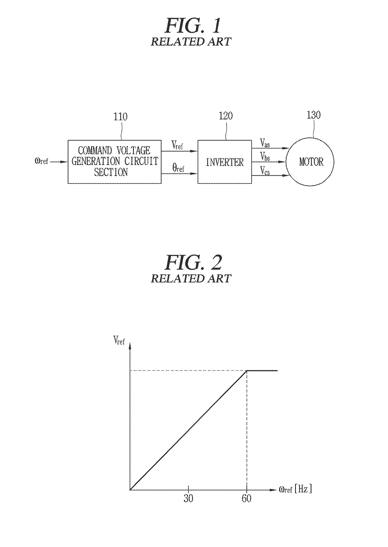
[0023]FIG. 1 is a block diagram schematically showing a conventional voltage / frequency control type inverter system.

[0024]When a user inputs a command frequency ωref, a command voltage generation circuit section 110 can determine a magnitude Vref and a phase angle θref of a command voltage of an inverter 120 corresponding to the command frequency ωref. The inverter 120 synthesizes three-phase pulse width modulation (PWM) voltages Vas, Vbs, and Vcs corresponding to a command voltage of a motor 130 based upon the magnitude Vref and phase angle θref of the command volta...


PUM


Abstract

The apparatus according to the present invention comprises a command voltage determination circuit section configured to determine a predetermined first compensation voltage as a command voltage upon initial startup and provide the command voltage to an inverter; a conversion circuit section configured to convert an output current of the inverter into a q-axis current on a synchronous reference frame; and a compensation voltage determination circuit section configured to determine a second compensation voltage based upon the q-axis current and to provide the second compensation voltage to the command voltage determination circuit section.

Description

CROSS-REFERENCE TO RELATED APPLICATION[0001]Pursuant to 35 U.S.C. § 119(a), this application claims the benefit of earlier filing date and right of priority to Korean Application No. 10-2017-0028277, filed on Mar. 6, 2017, the contents of which is incorporated by reference herein in its entirety.BACKGROUND OF THE INVENTION1. Field of the Invention[0002]The present invention relates to an inverter control apparatus.2. Background of the Invention[0003]Generally, an inverter is a power conversion device that receives commercial alternating current (AC) power, converts the AC power into direct current (DC) power, re-converts the DC power into AC power suitable for a motor, and supplies the AC power to the motor. Such an inverter efficiently controls a motor to decrease power consumption of the motor, thereby improving energy efficiency.[0004]In many application loads of industrial fields, an inverter is controlled by a voltage / frequency (abbreviated as “V / F” hereinafter) control method,...

Claims


Application Information

Patent Timeline
Patent Type & Authority Applications(United States)
IPC IPC(8): H02P21/04H02P21/34H02P27/04
CPCH02P21/04H02P21/34H02P27/047H02P27/08H02P1/028H02P1/28H02M1/36H02M7/44H02P27/06
Inventor BYUN, SUNGHOON
Owner LSIS CO LTD
Why Eureka
Try Eureka