High-frequency chip antenna measurement system

a technology of antenna measurement system and high-frequency chip, which is applied in the direction of antenna radiation diagram, measurement device, instruments, etc., can solve the problems of platform that cannot measure the radiation pattern on the x-y plane not on the y-z plane and the x-z plane, and the platform cannot measure the radiation pattern on the x-z and y-z plane not on the x-y plane, so as to improve the insufficiency of conventional measurement platform

Active Publication Date: 2014-05-22
NATIONAL CHUNG CHENG UNIV
View PDF4 Cites 5 Cited by
  • Summary
  • Abstract
  • Description
  • Claims
  • Application Information

AI Technical Summary

Benefits of technology

[0007]The primary objective of the present invention is to provide a high-frequency chip antenna measurement system, which can measure radiation patterns on x-z, y-z, and x-y planes to improve the insufficiency of the conventional measurement platforms.

Problems solved by technology

However, such platform can only measure the radiation pattern on the x-y plane not on the y-z plane and the x-z plane.
However, such platform can only measure the radiation pattern on the x-z and y-z planes not on x-y plane.

Method used


Image

  • High-frequency chip antenna measurement system
  • High-frequency chip antenna measurement system
  • High-frequency chip antenna measurement system

Examples


Embodiment Construction

[0027]Structural features and desired effects the present invention will become more fully understood by reference to a preferred embodiment given hereunder. However, it is to be understood that the embodiment is given by way of illustration only, thus are not limitative of the claim scope of the present invention.

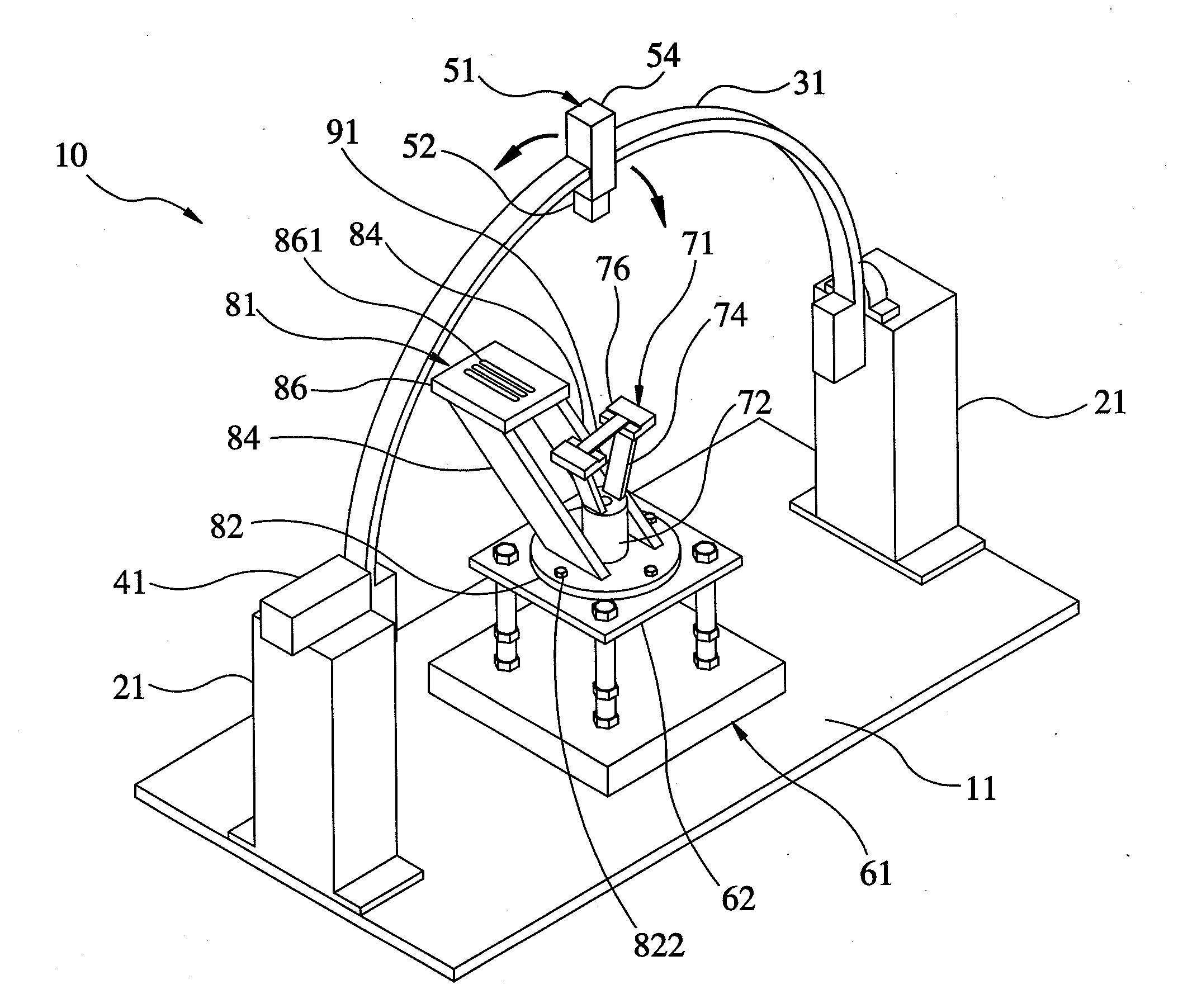
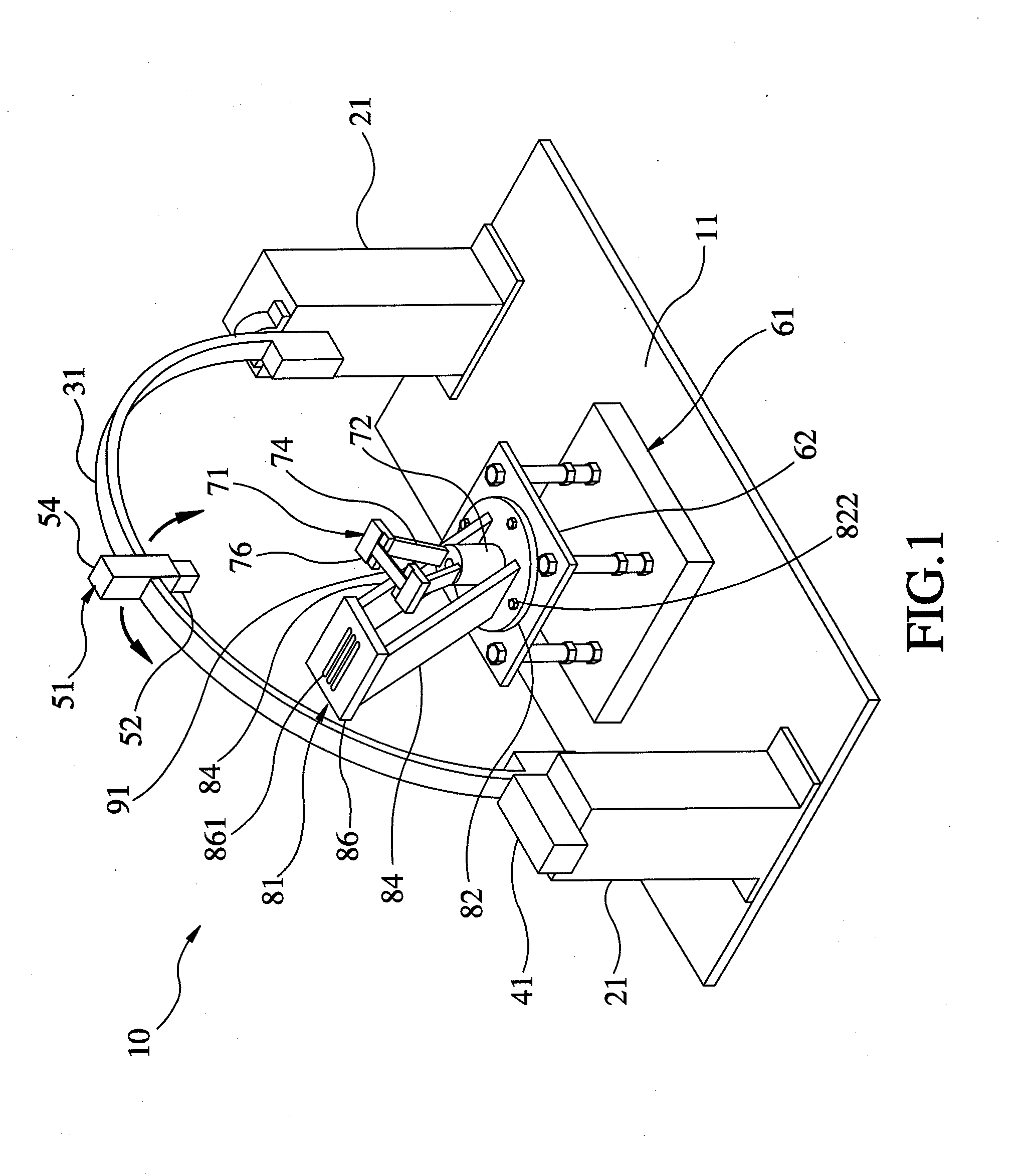
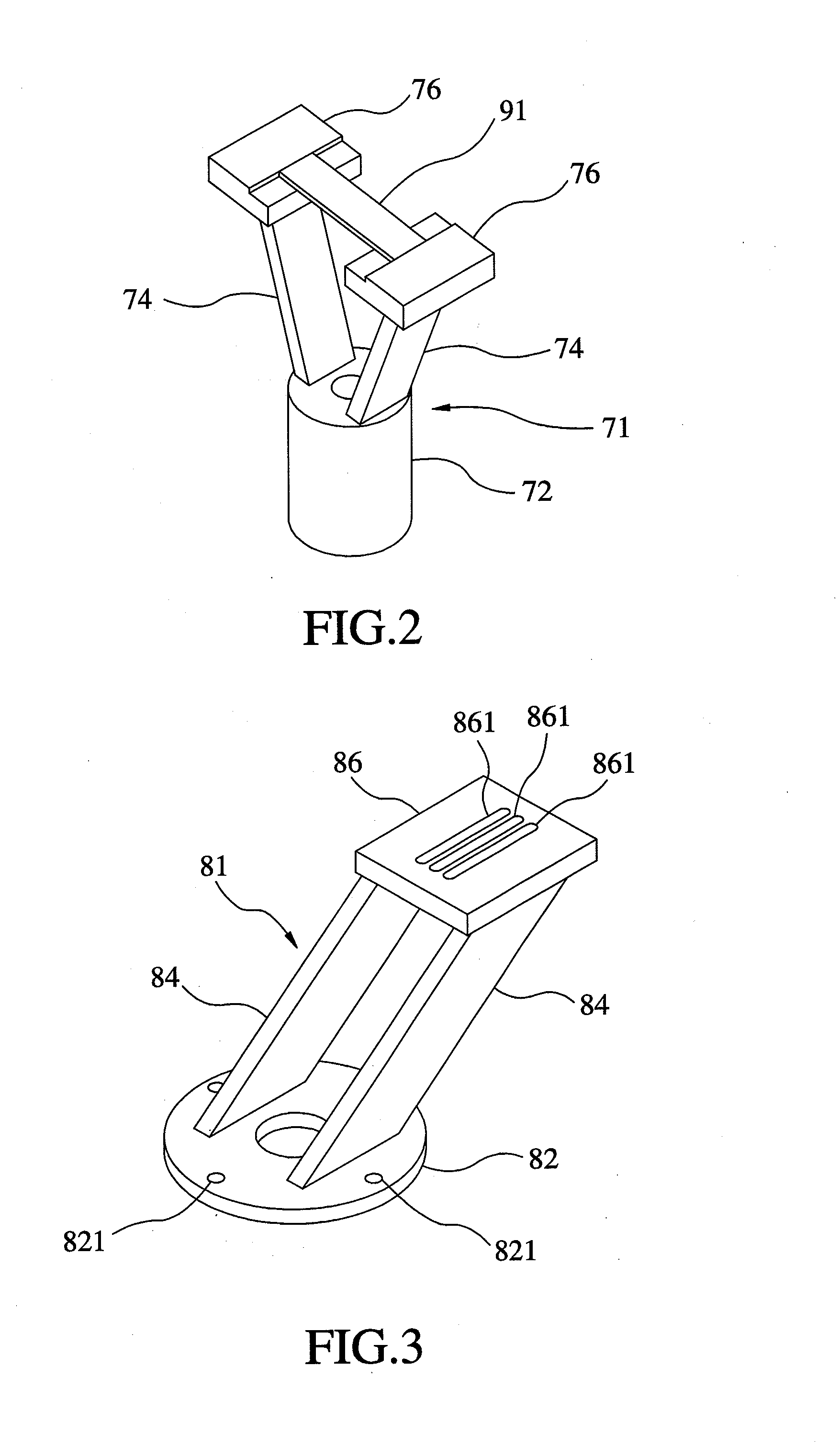
[0028]Referring to FIGS. 1-6, a high-frequency chip antenna measurement system 10 in accordance with a preferred embodiment of the present invention is composed of a platform 11, two piers 21, an arching 31, a stepper motor 41, an indication and fastening assembly 51, a carrier stage 61, a chip antenna carrier 71, a probe carrier 81, and a bridging member 91. The detailed descriptions and operations of these elements as well as their interrelations are recited in the respective paragraphs as follows.

[0029]The two piers 21 are mounted onto the platform 11. In this embodiment, the two piers 21 are columnar and can be shaped like something else.

[0030]The arching 31 includes t...


PUM


Abstract

A high-frequency chip antenna measurement system includes a platform; two piers; an arching; a stepper motor; an indication and fastening assembly having a source antenna holder and an illuminant indicator; a carrier stage; a chip antenna carrier having a support member and two sloping posts extending upward and outward from a top end of the support member, two chip antenna carrier benches being mounted to top ends of the two sloping posts respectively; a probe carrier having a support plate directionally variably fixed to the carrier substrate, two props fixed to the support member and parallel to each other and extending outward and upward slantingways, and a probe carrier bench mounted to top ends of the two props for bearing a probe; and a bridging member having two ends mounted to the chip antenna carrier benches.

Description

BACKGROUND OF THE INVENTION[0001]1. Field of the Invention[0002]The present invention relates generally to chip antenna measurement and more particularly, to a high-frequency chip antenna measurement system.[0003]2. Description of the Related Art[0004]The conventional chip antenna measurement platforms based on antenna far-field pattern measurement methods are constructed as shown in FIGS. 9-10, respectively.[0005]In the chip measurement platform 100 shown in FIG. 9, a source antenna 101 is fixed to a fastening pillar 103 located at one end of a chassis 102, a chip antenna 104 is mounted onto a carrier bench 105, and the carrier bench 105 is connected with a carrier pillar 106 located at the other end of the chassis 102. When it is intended for measurement, the source antenna 101 and a probe 107 are connected to a measuring instrument 109 via a high-frequency coaxial cable 108. The source antenna 101 can provide or receive electromagnetic energy for or from the chip antenna 104. The...

Claims


Application Information

Patent Timeline
Patent Type & Authority Applications(United States)
IPC IPC(8): G01R29/10
CPCG01R29/10
Inventor CHANG, CHIA-CHANCHANG, SHENG-FUHLIN, CHUN-CHIHSIEH, SHENG-CHI
Owner NATIONAL CHUNG CHENG UNIV
Why Eureka
Try Eureka