Low-speed motor

A low-speed motor and generator technology, applied in the direction of electric components, electromechanical devices, electrical components, etc., can solve the problem that the motor is not suitable for special purposes, and achieve the effect of reduced cost and high efficiency

Inactive Publication Date: 2005-06-29
智能发动机联合股份有限公司
View PDF0 Cites 1 Cited by
  • Summary
  • Abstract
  • Description
  • Claims
  • Application Information

AI Technical Summary

Problems solved by technology

But some of these motors are not suitable for special applica

Method used


Image

  • Low-speed motor
  • Low-speed motor
  • Low-speed motor

Examples


Embodiment Construction

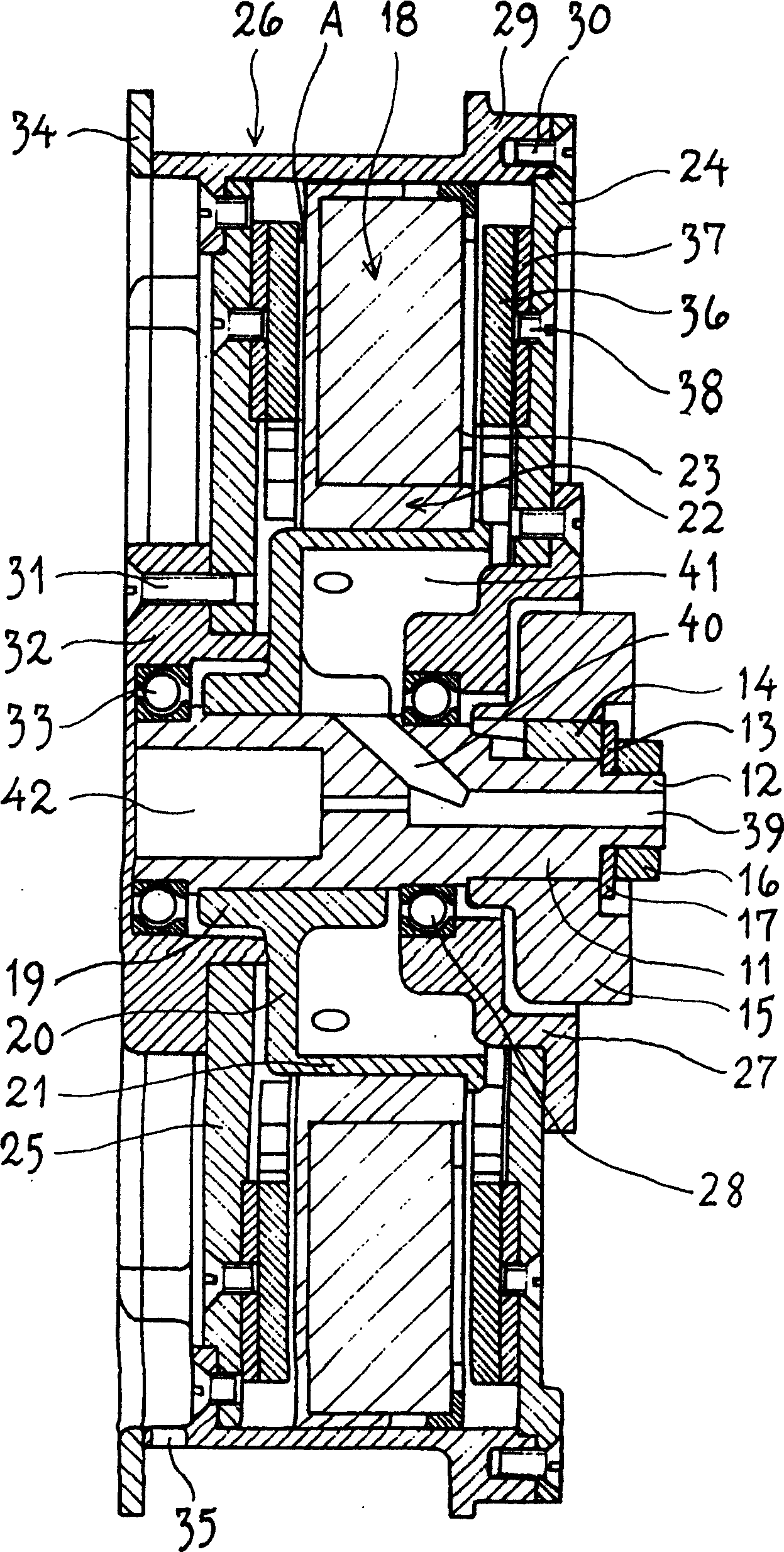
[0030] figure 1 The motor shown is one suitable for powering vehicles such as wheelchairs, trucks and other conveyors on wheels. The motor can be used periodically as a generator, eg for braking. The electric motor comprises a shaft 11 which is supported on the vehicle by a carrying arm 15 or corresponding bracket through an inner tapering end 12 with a keyway 13 and a key 14 . Locking is provided by a nut 16 with a washer 17 .

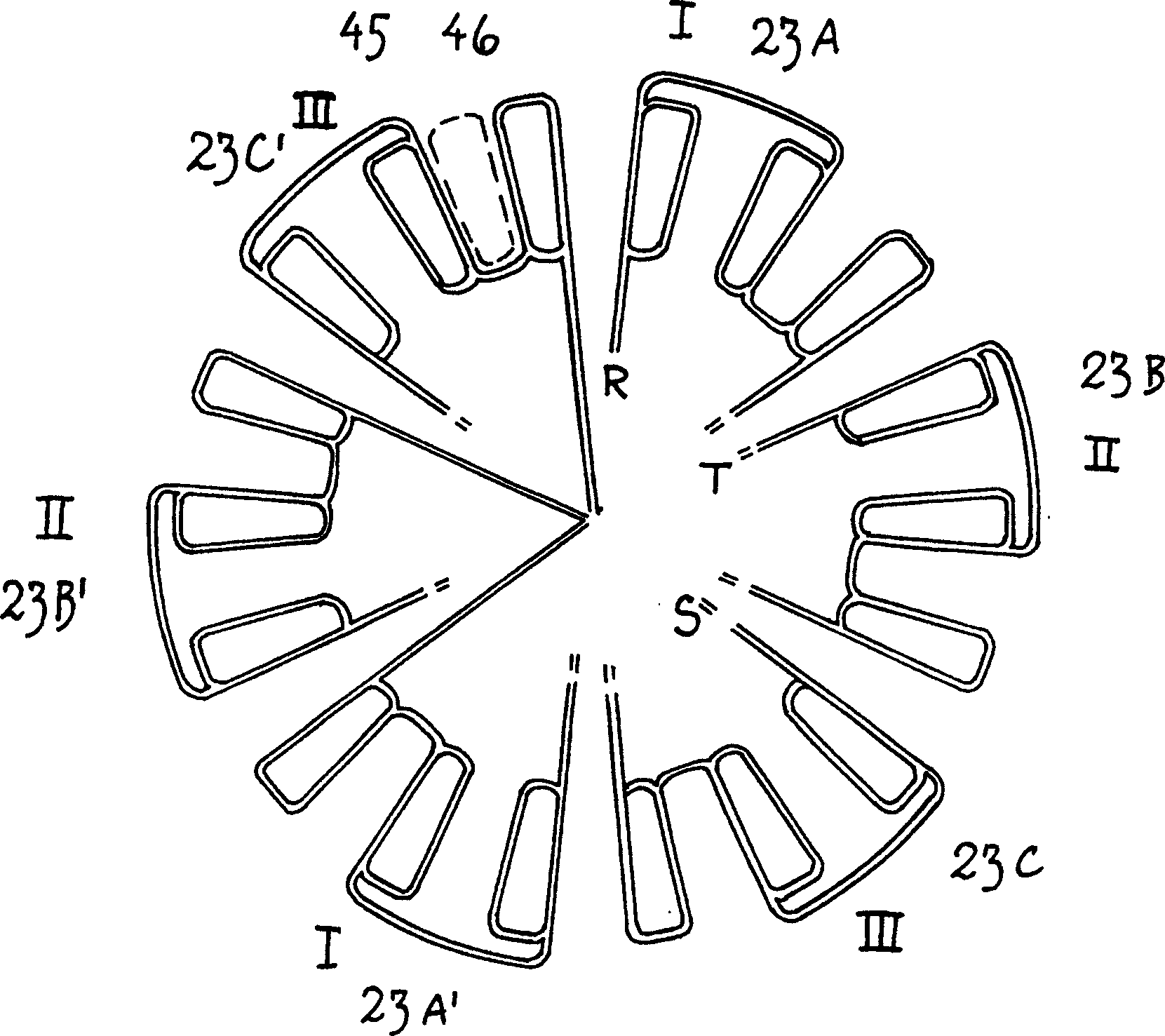
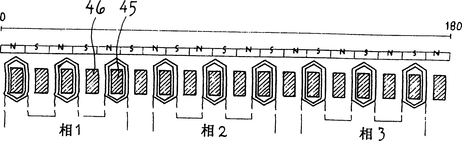
[0031] The shaft 11 has a stator part 18 and a rotating part, both of which are constructed of several parts. The stator part 18 comprises a hub 19 converging on the shaft with a radially central flange 20 which enters and carries a cylindrical stator bushing 21 which extends to the carrier arm 15, but in the axial direction of the carrier arm. end in distance. The stator bushing 21 has a plastic component 22 embedded with coils 23 scattered around it. In the illustrated embodiment, there are 18 spaced apart stator coils 23 . The stator coils, i...


PUM


Abstract

A low-speed electrical machine, such as an electric motor, a generator or a combined motor-generator, consists of a set of toroidal coils (23), a set of corresponding toroidal permanent magnets (36), especially a sinusoidal permanent magnet synchronous motor (PMSM ), the toroidal coil is on the iron core (45) of laminated sheets or extruded iron powder. The coils in the slots are concentrated rather than distributed; the winding core (45) and the core (46) without coils are alternately configured, and every two cores have a coil, and the number of slots or intervals between the cores is related to the number of magnetic poles. The number is different, the number of slots and the number of magnetic poles follow the following equation: |s-p|=2×m; s=12×n×m; where: s is the number of slots, p is the number of magnetic poles, n and m are natural numbers , the motor designed for three-phase voltage, the adjacent coils are connected in series, each phase has 2×m groups, which can be connected in series or in parallel. The electric motor can be used as a vehicle wheel motor.

Description

technical field [0001] The present invention relates to a low-speed motor, namely a motor, a generator or a combined motor-generator consisting of a set of annular coils on a laminated or extruded iron powder core and a set of corresponding annular permanent magnets. Background technique [0002] A low-speed motor can be used for different purposes, such as in land or sea vehicles for lifting, hoisting equipment, and in some areas for power generation. This motor is commonly referred to as a "Permanent Magnet Synchronous Motor" (PMSM). However, some motors of this type are not suitable for special applications, especially in conditions of high power and space requirements. [0003] Due to the problems of energy supply and energy costs, the demand for energy saving is gradually increasing. This is especially true for motor / generator applications in battery powered vehicles or other applications. In order to reduce the requirement on the battery capacity, expand the operati...

Claims


Application Information

Patent Timeline
IPC IPC(8): H02K21/26H02K1/02H02K3/28H02K3/46H02K21/12H02K21/24
CPCH02K3/28H02K21/24
Inventor 比约恩·克里斯托弗森
Owner 智能发动机联合股份有限公司
Why Eureka
Try Eureka