Torque transmission device for a motor vehicle

a transmission device and motor vehicle technology, applied in mechanical equipment, transportation and packaging, gearboxes, etc., can solve the problems of unsatisfactory devices in terms of efficiency, excessive size and weight, and particularly harmful drag torque, so as to reduce or even eliminate the drag torque in the first clutch, avoid excessive spinning, and improve energy efficiency

Pending Publication Date: 2022-05-12
VALEO EMBRAYAGES SAS
View PDF5 Cites 0 Cited by
  • Summary
  • Abstract
  • Description
  • Claims
  • Application Information

AI Technical Summary

Benefits of technology

[0018]The use of the clutches, particularly progressive multi-disk clutches, also makes it possible to ensure user comfort by avoiding sudden gear changes, together with perceptible changes in acceleration.
[0019]In addition, the connection element makes it possible to interrupt the driving of the output element of the first clutch, and particularly the output friction disks of the first clutch, when the second clutch is closed. This makes it possible to significantly limit, or even eliminate, the drag torque in the first clutch when the second clutch is closed, which makes it possible to improve the energy efficiency.
[0020]In addition, when the first transmission mechanism is a speed reducer with a low gear ratio and / or when the ratio between the reduction ratio of the second transmission mechanism and the reduction ratio of the first transmission mechanism (also referred to as the opening ratio of the gearbox) is high, for example between 1.3 and 2, and all the more so when the first and second input elements of the clutches are driven directly, without an intermediate reduction gear, by an electric motor that can rotate at up to 15,000 revolutions per minute, the opening of the connection element makes it possible to avoid excessive spinning of the first output element of the first clutch, which could rotate at a higher speed than the motor (the speed of which is already very high) when the second clutch is closed and the first clutch is open. In fact, the first transmission mechanism would act as a speed multiplier in relation to the first output element of the first clutch when the torque is transmitted by the second clutch.
[0021]The invention therefore makes it possible to improve the safety of the torque transmission device. For example, with an electric motor rotating at 15,000 revolutions per minute and an opening ratio of 2 between the first and second transmission mechanisms, the first output element of the first clutch could for example rotate at 30,000 revolutions per minute in the absence of a connection element arranged to interrupt the drive between the first output element and the transmission member. This rotating speed of the first output element is likely to create problems relating to mechanical strength and could generate malfunctions in the first clutch.

Problems solved by technology

This device is unsatisfactory in terms of efficiency, as drag torque occurs on one of the clutches, which is open when the other clutch is closed.
This drag torque is particularly detrimental when the clutches are wet.
In addition, the clutches of this device transmit relatively high torque, which means that the clutches must be a considerable size and weight, and therefore results in a large footprint linked to the clutches.

Method used


Image

  • Torque transmission device for a motor vehicle
  • Torque transmission device for a motor vehicle
  • Torque transmission device for a motor vehicle

Examples


first embodiment

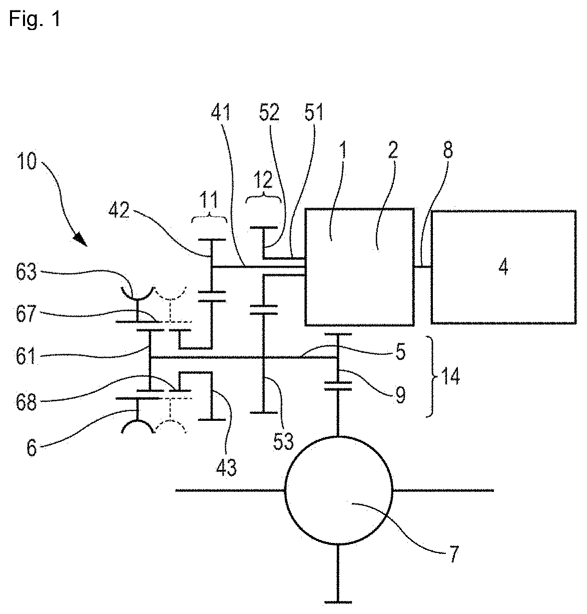
[0143]FIG. 1 is a block diagram illustrating the invention. FIG. 1 illustrates a torque transmission system comprising an electric motor 4 of a vehicle capable of propelling the vehicle, and a torque transmission assembly.

[0144]The torque transmission assembly includes a transmission device 10 and a differential 7 capable of driving two laterally opposite wheels of the vehicle. The torque transmission device 10 comprises an output member 9 coupled to the differential 7.

[0145]The torque transmission device 10 includes:[0146]a first clutch 1 comprising a first input element capable of being driven by the motor 4, and a first output element, torque being transmitted between the first input element and the first output element when the first clutch is closed,[0147]a second clutch 2 comprising a second input element capable of being driven by the motor, and a second output element, torque being transmitted between the second input element and the second output element when the second clu...

second embodiment

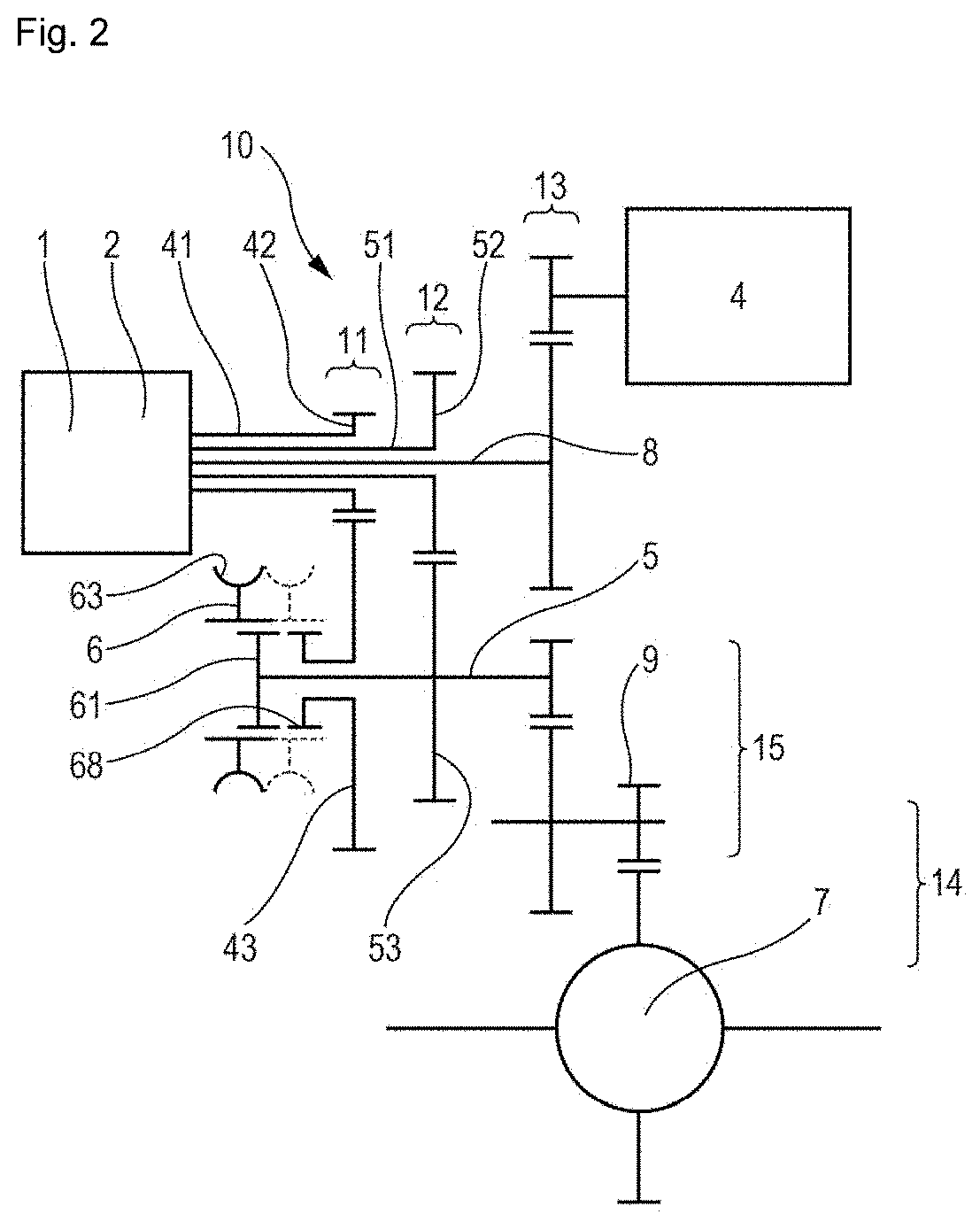
[0181]In the second embodiment shown schematically in FIG. 2, there is a first common reduction gear 13 arranged kinematically between the motor 4 and the dual clutch 1, 2. This common reduction gear is formed by a gear train. A second two-stage common reduction gear 15, 14 is also formed by a gear train between the transmission member 5 and the differential 7.

third embodiment

[0182]In the third embodiment shown in FIG. 4, there is a two-stage common reduction gear 15, 14 also formed by a gear train between the transmission member 5 and the differential 7.

[0183]In addition to these differences, the second embodiment in FIG. 2 is distinguished in that the first transmission mechanism 11 and the second transmission mechanism 12 are situated between the motor 4 and the first and second clutches 1, 2. In addition, the second input shaft 51 is a hollow shaft and the common torque input shaft 8 extends inside the hollow shaft 51.The three shafts 8, 51 and 41 are thus arranged inside each other, the common input shaft 8 extending inside the second input shaft 51, which extends inside the first input shaft 41. The footprint is thus limited.

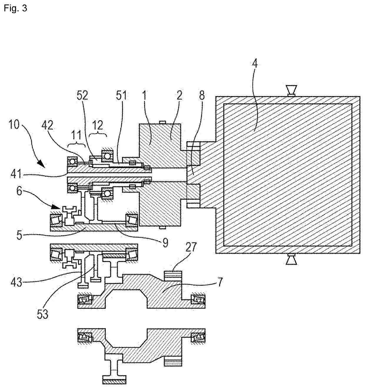
[0184]In the first embodiment shown schematically in FIG. 3 and in the third embodiment shown in FIG. 4, the torque transmission assembly further comprises a parking brake mechanism including a toothed locking wheel 27 mounted ...


PUM


Abstract

A torque transmission device for a vehicle including at least one motor, the torque transmission device including a first clutch, a second clutch and a transmission member. A first transmission mechanism is provided between the first clutch and the transmission member, and a second transmission mechanism is provided between the second clutch and the transmission member. A connection element arranged to permit or interrupt the mutual rotational drive between the first output element of the first clutch and the transmission member, by means of the first transmission mechanism.

Description

TECHNICAL FIELD OF THE INVENTION[0001]The invention relates to a torque transmission device for an electric or hybrid vehicle, particularly for an electric or hybrid motor vehicle.PRIOR ART[0002]The invention applies more particularly to hybrid vehicles and to electric vehicles. The speed of an electric motor can be high, greater than or equal to 15,000 revolutions per minute for example, particularly for two-speed electric transmission lines.[0003]To adjust the speed and the torque, the use of electric motors generally requires a transmission including a speed reduction device that makes it possible to achieve the desired speed and torque output levels at each wheel, and a differential to vary the speed between two laterally opposite wheels.[0004]To adapt to the different vehicle speeds, it is known to use clutches that make it possible to select the desired reduction ratio on the speed reduction device. Such a device is disclosed in DE102016202723, for example.[0005]This device is...

Claims


Application Information

Patent Timeline
Patent Type & Authority Applications(United States)
IPC IPC(8): F16H3/00F16H61/00F16H61/02
CPCF16H3/006F16H61/0025F16H2200/0034F16H2200/0021F16H61/0206
Inventor MAUREL, HERVETERMENON, NORBERTOJIVAN, CAMELIAGUINOT, THIERRYPECOUL, JEAN-CHRISTOPHE
Owner VALEO EMBRAYAGES SAS
Why Eureka
Try Eureka