Adapter for a corvette rear differential

a technology for adapters and rear differentials, which is applied in the direction of control devices, vehicle components, transportation and packaging, etc., can solve the problem of not being able to cross-over without modification of drive train and body

Inactive Publication Date: 2012-08-14
CHASSIS CONCEPT
View PDF13 Cites 0 Cited by
  • Summary
  • Abstract
  • Description
  • Claims
  • Application Information

AI Technical Summary

Benefits of technology

[0025]A front boss, which extends forward from the front (outside) face of the housing block, receives the outside (front) bearing race and its bearing and permits the overall weight of the housing structure to be reduced by permitting a reduction in the thickness of the projecting ears and the thickness of the wall build-out mounting structures. In addition, the boss has a thinner wall than the body of the housing, which permits more heat to dissipate from the front (outside) bearing region, thereby permitting the use of a smaller front bearing, than with the rear bearing which is positioned within the main body of the housing.
[0027]The bore has two internal annular shoulders with different through bore diameters which are stepped from one to the other, with the inner (rear) shoulder having the smaller (bore diameter) opening and the outer (front) shoulder having the larger (bore diameter) opening. The inner shoulder operates as the abutment stop for both the front and rear bearing races. The longitudinal thickness of this shoulder establishes the spacing between the outside and inside bearings.

Problems solved by technology

While more and more Corvette enthusiasts are requesting C5 or C6 rear suspensions in their rebuilt older generation vehicles because of the better handling and ride, such crossover use is not possible without modification to the drive train and body.

Method used


Image

  • Adapter for a corvette rear differential
  • Adapter for a corvette rear differential
  • Adapter for a corvette rear differential

Examples


Embodiment Construction

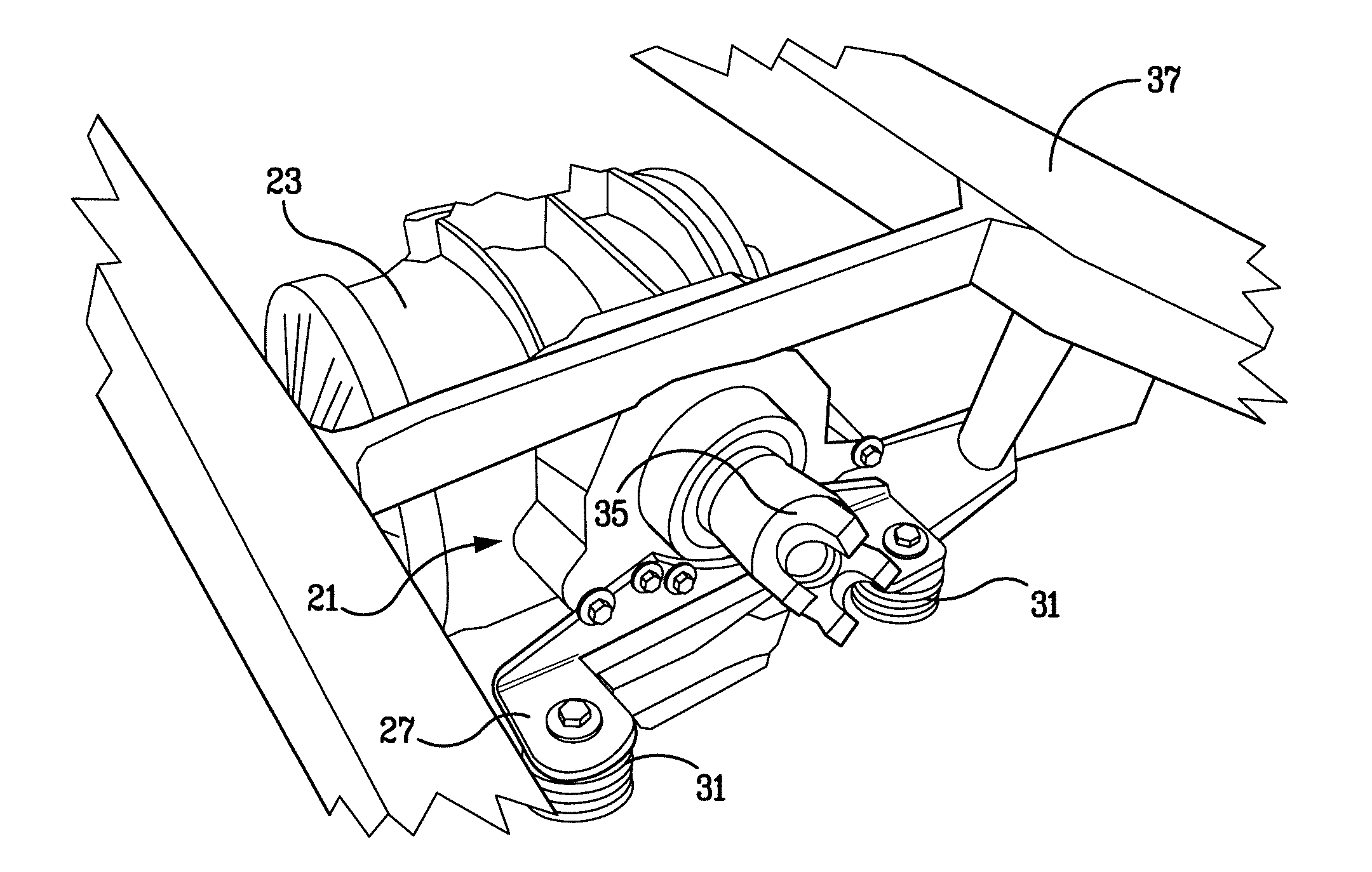
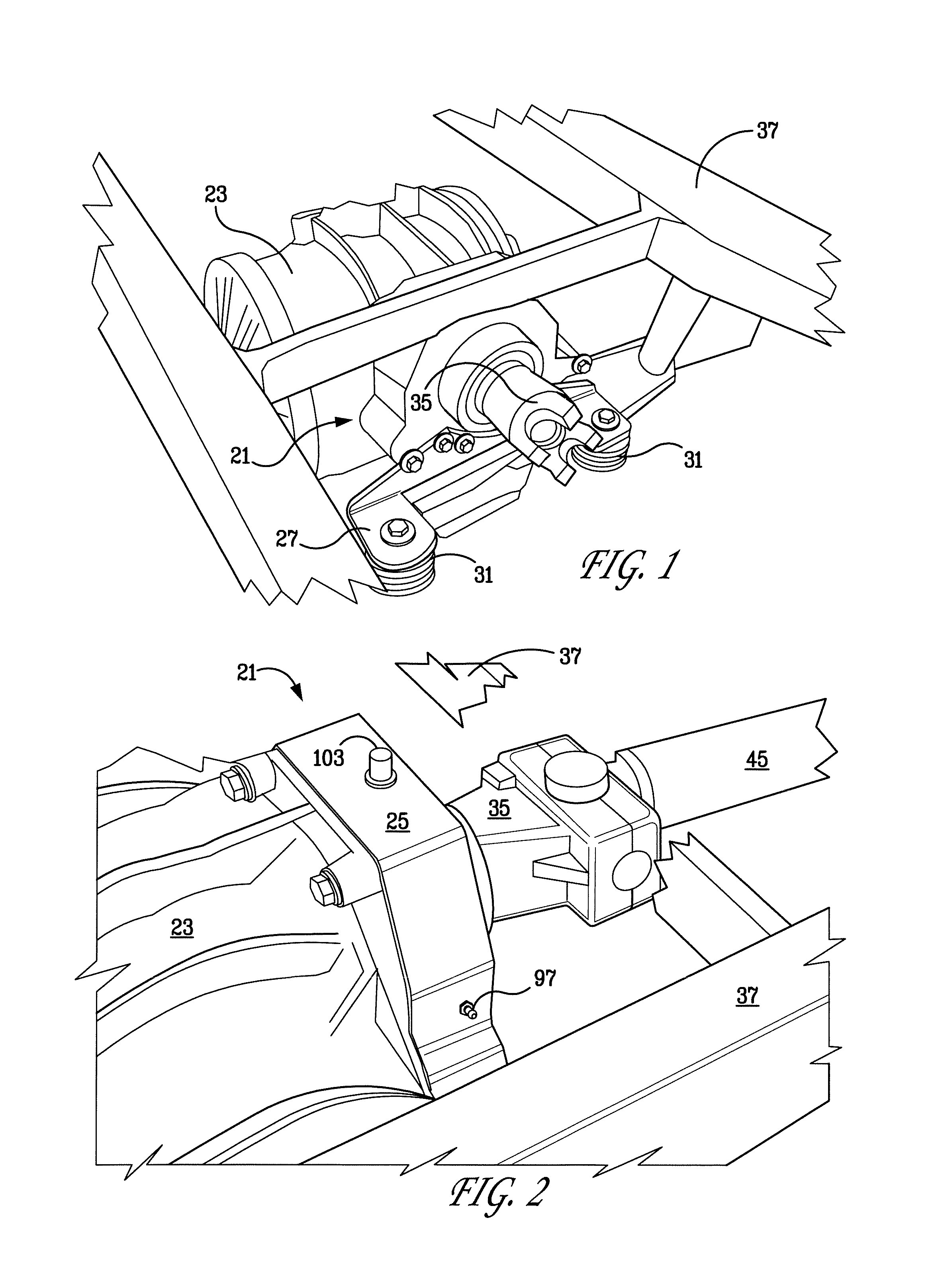
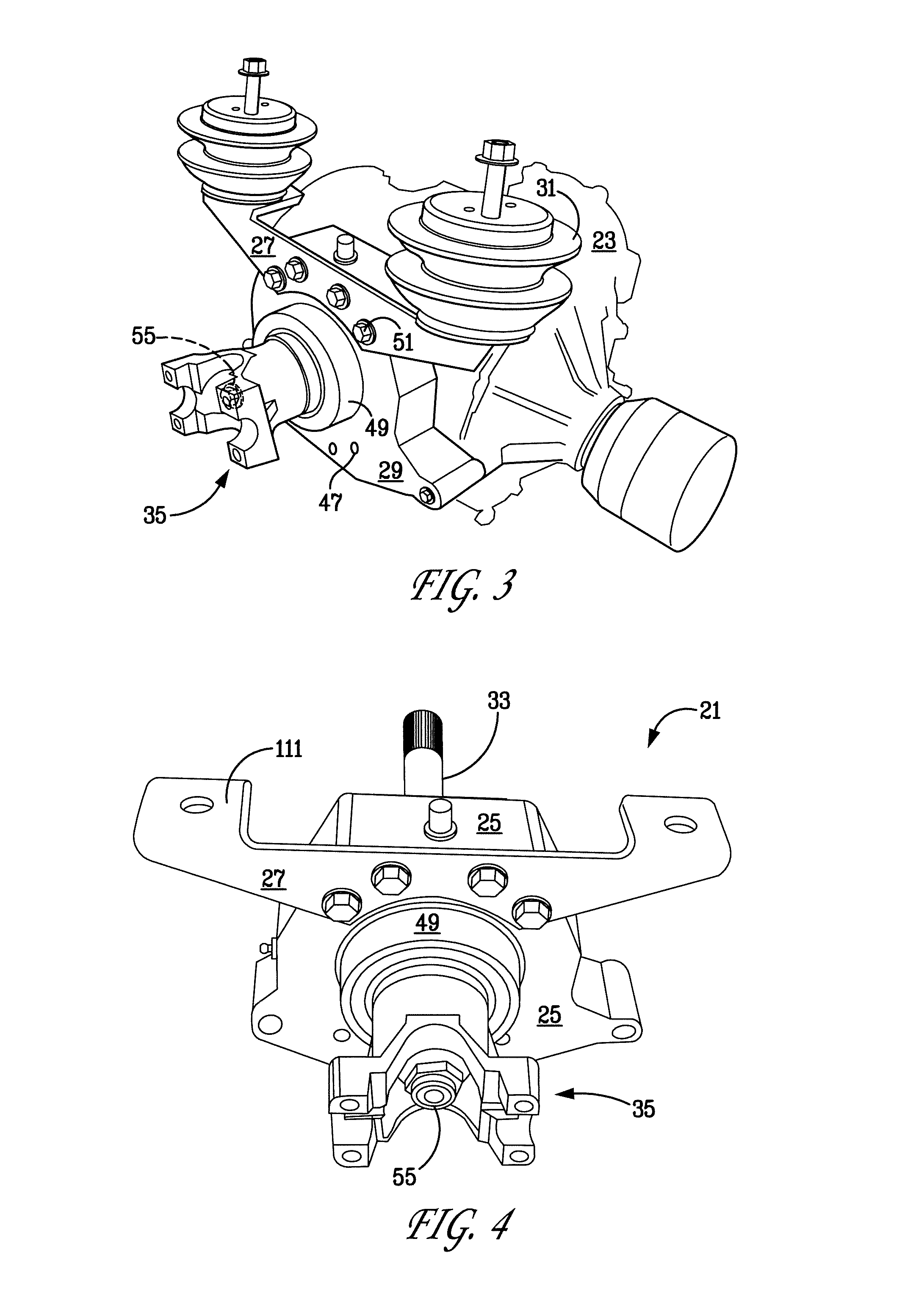
[0055]The present invention is an adaptor 21, FIG. 1, for mating the front mounted engine and transmission of an older generation Corvette to a newer generation, specifically a C5 or C6 rear differential and suspension. The adaptor 21, FIG. 1, bolts to the front of a C5 or C6 differential 23 in place of the removed O.E.M. transmission. The adaptor 21 includes a housing 25, FIGS. 1-2. A bracket 27 is bolted to the front face 29 of the housing 25. This bracket 27 also bolts to frame mounts 31. This bracket 27 can be bolted below a shaft 33 (not shown in FIG. 1) and coupling yoke 35 as shown in FIG. 1, or above them, depending upon the geometry of the vehicle frame 37 and the mounting configuration of the rear suspension assembly of which the differential 23 is a part.

[0056]The adaptor 21 assembly, FIGS. 2-8, and in particular, the housing 25 carries a pair of threaded holes 39 (not shown in FIG. 2) near the top of its rear / inside face 41 and another near the bottom (not shown in FIG. ...


PUM


Abstract

An adaptor for an older Corvette drive train provides a structure for coupling the drive shaft extending from a front-mounted transmission to the differential of a C5 or C6 Corvette rear suspension in which the rear mounted transmission has been removed. A housing holds a stub shaft for rotation on front (outside) and rear (inside) bearings. The shaft has a coupling yoke mounted to its front end and engages the differential gearing at its other (rear) end. The housing mounts to the differential at the five mounting points of the removed transmission. A bracket which attaches to frame mounts can be mounted to either the top or bottom front (outside) face of the housing, depending upon the suspension-to-frame geometry. A circular flange on the shaft positions and holds the inside bearing and a rearward extending boss on the yoke positions and holds the outside bearing. A crushable tubular spacer fits over a portion of the shaft and holds the front and rear bearings apart during assembly and while the shaft assembly is drawn up. Two grease ports and fittings access the interior of the peripheral sealing ring to meet and seal the differential opening.

Description

FIELD OF THE INVENTION[0001]This invention is related to automotive drive train adaptors, specifically an adaptor which permits the mating of drive train components not normally designed to be connected.BACKGROUND OF THE INVENTION[0002]The present invention is directed to an adaptor which permits a Chevrolet Corvette C5 or C6 rear end assembly to be used in a rebuild of an older Corvette, such as a C1, C2, or C3 generation model.[0003]The Corvette has had six generations of vehicle design, typically known in the industry as C1 through C6, with the C1 being produced from 1953 to 1962, the C2 being produced from 1963 to 1967, the C3 being produced from 1968 to 1982, the C4 being produced from 1984 to 1996, the C5 being produced from 1997 to 2004, and the C6 being produced from 2005 to date.[0004]Each generation has maintained a fundamental design in its body, suspension, drive train, and engines, with changes being introduced from model year to model year within a generation to meet p...

Claims


Application Information

Patent Timeline
Patent Type & Authority Patents(United States)
IPC IPC(8): B60K17/00
CPCB60K17/22
Inventor LEICHT, SR., RAYMOND LEWIS
Owner CHASSIS CONCEPT
Why Eureka
Try Eureka