Power amplifier

a power amplifier and amplifier technology, applied in the field of power amplifiers, can solve the problems of variable power supply rise/fall times and delays, ee&r amplifiers use an expensive and complex the overall cost and complexity of variable switching variable power supply, so as to achieve the effect of reducing power discontinuities between the two power levels, reducing power discontinuities, and increasing power

Active Publication Date: 2008-04-03
ZARBANA DIGITAL FUND
View PDF6 Cites 4 Cited by
  • Summary
  • Abstract
  • Description
  • Claims
  • Application Information

AI Technical Summary

Benefits of technology

[0007] In accordance with one aspect of the invention, a circuit for controlling power delivery to an amplifier is provided. The circuit includes a first voltage source for transmitting a first fixed voltage to the amplifier; a second voltage source for transmitting a second fixed voltage to the amplifier, the second fixed voltage being a lower value than the first voltage; and a control element having one control input signal for transitioning between the two voltage sources and connecting at least one of the voltage sources to the amplifier. The control element causes the amplifier to receive a transitional voltage from one respective voltage source substantially equal to the fixed voltage previously transmitted from the other respective voltage source, such that a transitional overlap in fixed voltage values results in a reduction in transitional discontinuities. The control elements are controlled so that there is adequate head room for the envelope of the signal.
[0009] The circuit's first and second variable series pass elements can be connected in a source a follower configuration. The circuit can further include an envelope detector. The envelope detector can be a digital signal processor. The circuit's amplifier can be a Class F amplifier. The control element includes a controllable resistance element in some circuit embodiments. It can also be a lossy control element, which includes at least two transistors. In some circuits, each transistor is in electrical communication with at least one voltage source. In a specific circuit embodiment, one transistor is in communication with the first voltage source and the other transistor is in electrical communication with the second voltage source. Additionally, the envelope detector can control the control element such that an envelope signal is reproduced at the shared connection, which substantially gains and offsets set for improved efficiency and linearity.
[0010] The voltage supplied to the amplifier through the control element can have the beneficial effect of making the amplifier more linear. For example, if the amplifier demonstrates gain expansion when operating from a fixed power supply (class B, C, E, and F amplifiers typically do), the control of the power supply tends to reduce the amount of the gain expansion, rendering a more linear amplifier.
[0011] In accordance with another aspect of the invention, a method for amplifying a signal is provided. The method includes the steps of receiving an input signal having an associated input signal envelope; detecting the input signal envelope; establishing a voltage threshold in response to the signal envelope; while the input signal envelope is below the threshold, amplifying the input signal by energizing an amplifier with at least one fixed voltage received from a first power supply; and when the signal envelope exceeds the threshold, transitioning to a second fixed voltage from a second power supply, which generates a second fixed voltage, such that the transitioning is substantially smooth and so that the amplifier continues to have adequate head room.
[0013] In accordance with still another aspect of the invention, a method for powering an amplifier is provided. The method includes the steps of transmitting a first fixed DC power level from a first power supply through a series pass element to an amplifier; transmitting a second fixed DC power level from a second power supply through a series pass element to the amplifier; transitioning between the two power supplies such that the amplifier receives one DC power level from one of the power supplies in response to a signal envelope; and transitioning between the two power supplies such that the amplifier receives one DC voltage level from one of the power supply to accommodate higher envelopes. levels through a substantially smooth transition such that power discontinuities between the two power levels are substantially reduced, the transitioning regulated by a two component control element.
[0014] The amplifier can be a Class F or a Class E amplifier. In one embodiment of the method, transitioning between the two power supplies results in substantially continuous transitions between the two fixed power levels. The step of transitioning between the two power supplies can dissipate more power than a unitary variable switching power supply. Moreover, the control element can include at least one of a transistor or a diode. The step of controlling the series pass transistors adjusts the voltage received by the amplifier as the amplitude (envelope) of the RF signal varies to optimize the efficiency and linearity of the amplifier.

Problems solved by technology

Typically, EE&R amplifiers use an expensive and complex switching variable power supply.
Switching speed needs to be much higher than the baseband bandwidth, making it expensive.
Also, the variable power supply needs to have rise / fall times and delays much faster than envelope transition times. These factors contribute to the overall expense and complexity of variable switching power supplies.
In the past, multiple power supplies have been proposed in lieu of the variable power supply used in EE&R systems, but in such embodiments discrete and abrupt switching occurs between supplies.
These approaches can cause switching discontinuities and steps.

Method used


Image

  • Power amplifier
  • Power amplifier
  • Power amplifier

Examples


Embodiment Construction

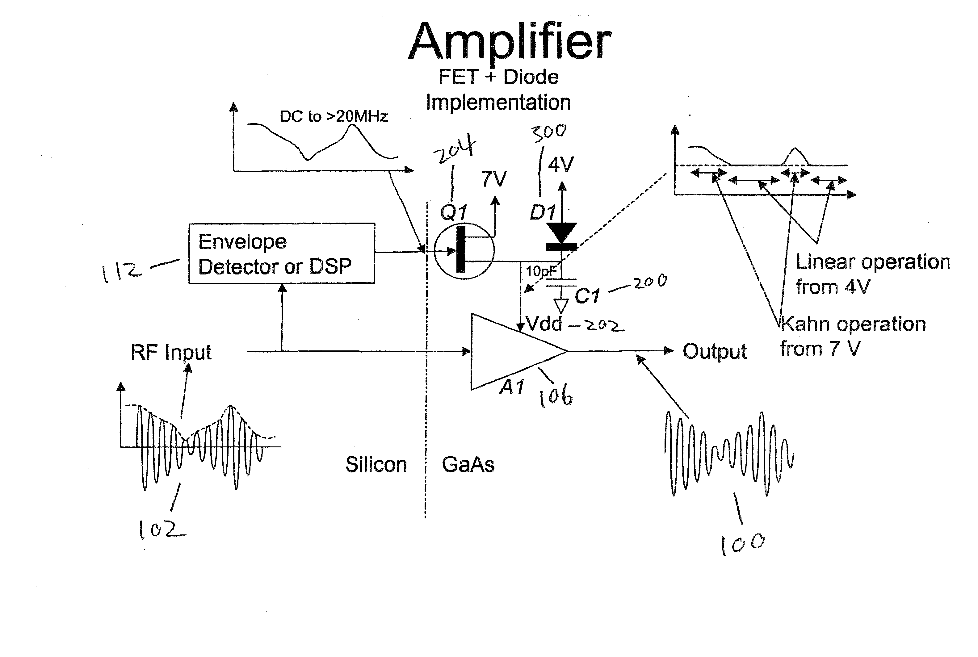
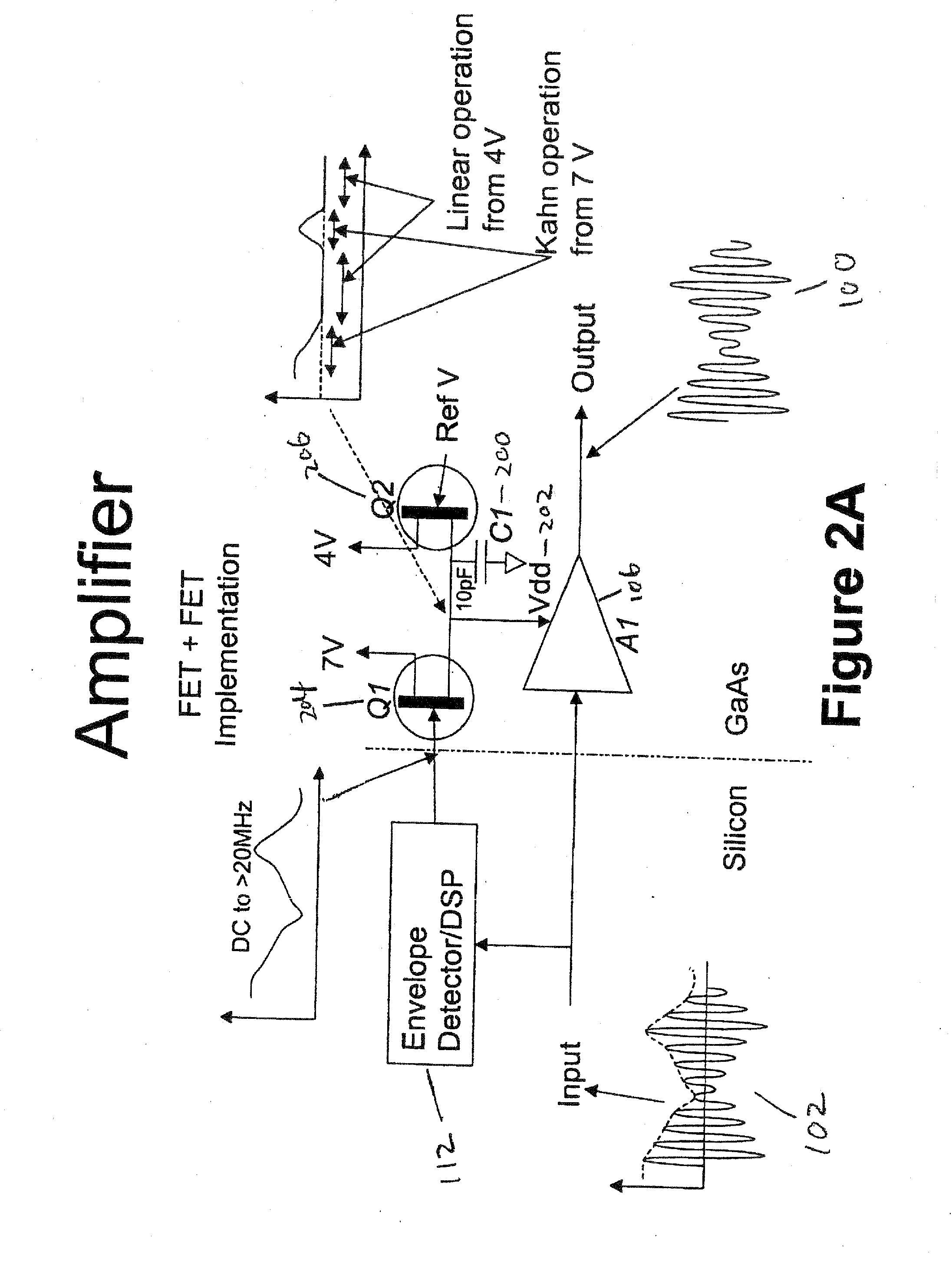
[0020] In various embodiments of the invention, improved methods and systems for amplifying a signal are provided. Specifically, systems and methods for amplifying a signal through a lossy switch element tied to two or more voltage sources are provided. In the preferred embodiment, envelope information from the signal is used to smoothly transition between the two or more voltage sources to provide signal amplification over an increased range.

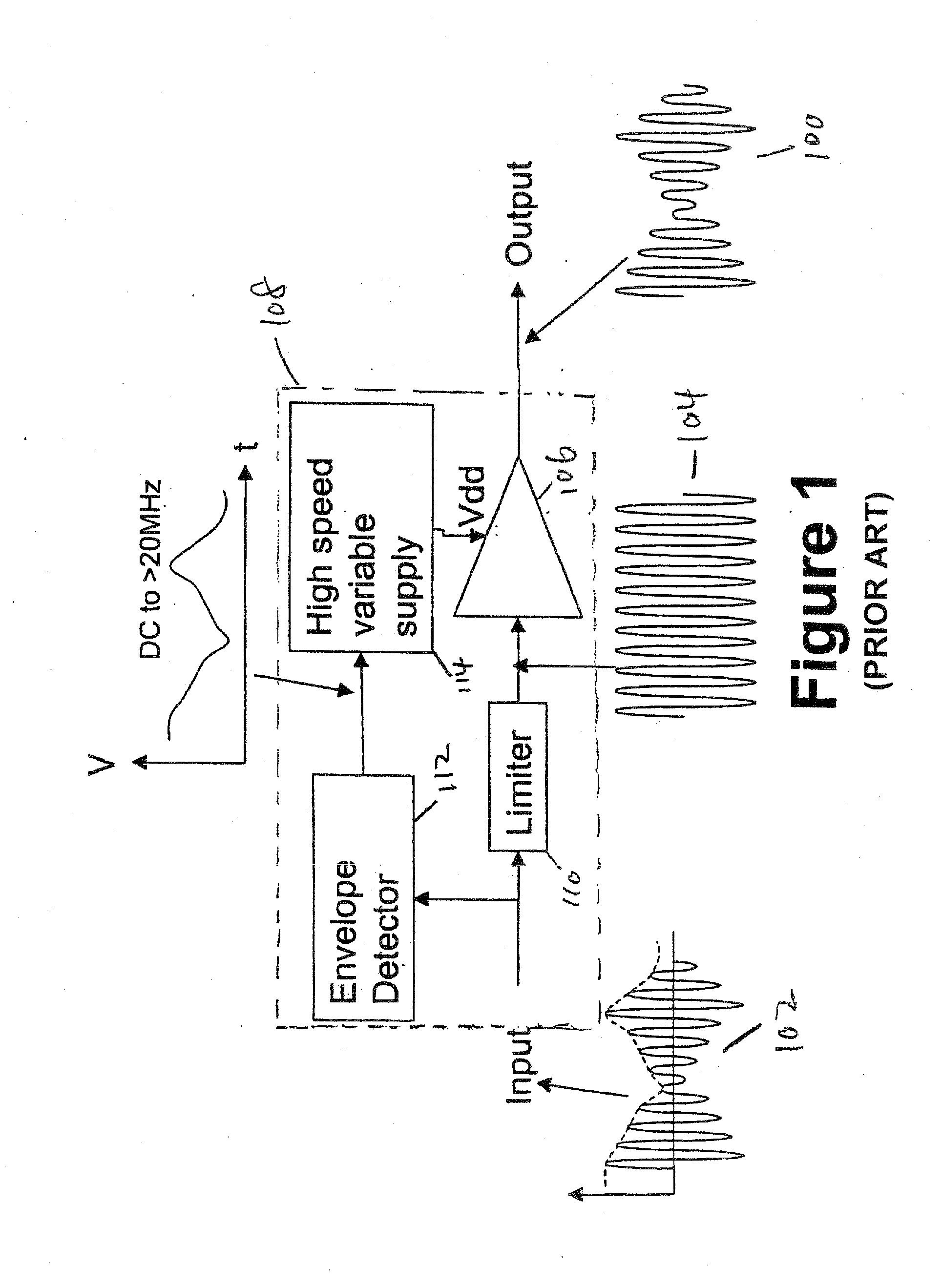
[0021] For signals having a large peak-to-average power ratio, linear power amplifiers become very low in power-added efficiency. This is because the amplifier must be backed off (at its input) most of the time from the signal level providing its highest efficiency. This is necessary in order to be able to amplify the signal during its peak power without clipping.

[0022] Another technique for signals having a large peak-to-average power ratio is the Kahn architecture (also called “Envelope Elimination and Restoration” or EE&R). Here, the input...


PUM


Abstract

Improved methods and systems for amplifying a signal are provided. Specifically, systems and methods for amplifying a signal through a lossy switch element tied to two or more voltage sources are provided. In the preferred embodiment, envelope information from the signal is used to smoothly transition between the two or more voltage sources to provide signal amplification over an increased range.

Description

CROSS-REFERENCE TO RELATED APPLICATION [0001] This application is a continuation of U.S. pending application Ser. No. 11 / 268,765, filed Nov. 7, 2005, both of which claim the benefit of U.S. Provisional Patent Application No. 60 / 625,301 filed Nov. 5, 2004 the entire disclosure of which is incorporated herein by reference.FIELD OF THE INVENTION [0002] The invention relates generally to the field of power amplifiers. Specifically, the invention relates to power supply configurations and related methods suitable for powering an amplifier while substantially reducing switching discontinuities. In particular, embodiments of the invention are suitable for powering an RF power amplifier in a high efficiency and high linearity mode. BACKGROUND OF THE INVENTION [0003] Various amplifiers and power supplies are implemented using Envelope Elimination and Restoration (EE&R) techniques. The Kahn amplifier represents one such implementation of the EE&R techniques. An exemplary EE&R system is shown ...

Claims


Application Information

Patent Timeline
Patent Type & Authority Applications(United States)
IPC IPC(8): H03G3/20
CPCH03F1/0211H03F2200/102H03F1/0261
Inventor GRUNDLINGH, JOHAN M.
Owner ZARBANA DIGITAL FUND
Why Eureka
Try Eureka