Traffic sensing and monitoring apparatus

Active Publication Date: 2010-01-26
OPTASENSE HLDG LTD
View PDF11 Cites 35 Cited by
  • Summary
  • Abstract
  • Description
  • Claims
  • Application Information

AI Technical Summary

Benefits of technology

[0007]It is an object of the invention to ameliorate at least one of these problems. According to a first aspect of the invention, this object is achieved by traffic monitoring apparatus comprising a length l of optical fibre, means arranged to introduce a series of pulse pairs into an input end of the length, each of the pulse pairs comprising first and second pulses of radiation having a frequency difference Ω and the second pulse being delayed with respect to the first by a delay τ, and the apparatus further comprising a photodetector arranged to detect radiation which is Rayleigh-backscattered within the length of fibre towards the input end and to generate an output signal in response thereto. In use, the length of optical fibre is deployed on or beneath a surface for carrying vehicles such that the weight of a vehicle using the surface may act on the length. A moving vehicle located above a section of the length of fibre defined by positions at which respective portions of the first and second pulses of each pulse pai

Problems solved by technology

At present, apparatus for sensing and monitoring road traffic provides only sparse information concerning traffic conditions along roads due to the expense and limited range of current traffic sensing and monitoring apparatus.
CCTV systems only provide clear views of traffic over distances of approximately 50 m. Inductive loop sensors can only provide information at a point and are generally only installed in roads using a relatively large separation (e.g. 500 m) between consecutive sensors because a higher linear density of sensors is prohibitively expensive.
These types of apparatus can only provide t

Method used


Image

  • Traffic sensing and monitoring apparatus
  • Traffic sensing and monitoring apparatus
  • Traffic sensing and monitoring apparatus

Examples


Example

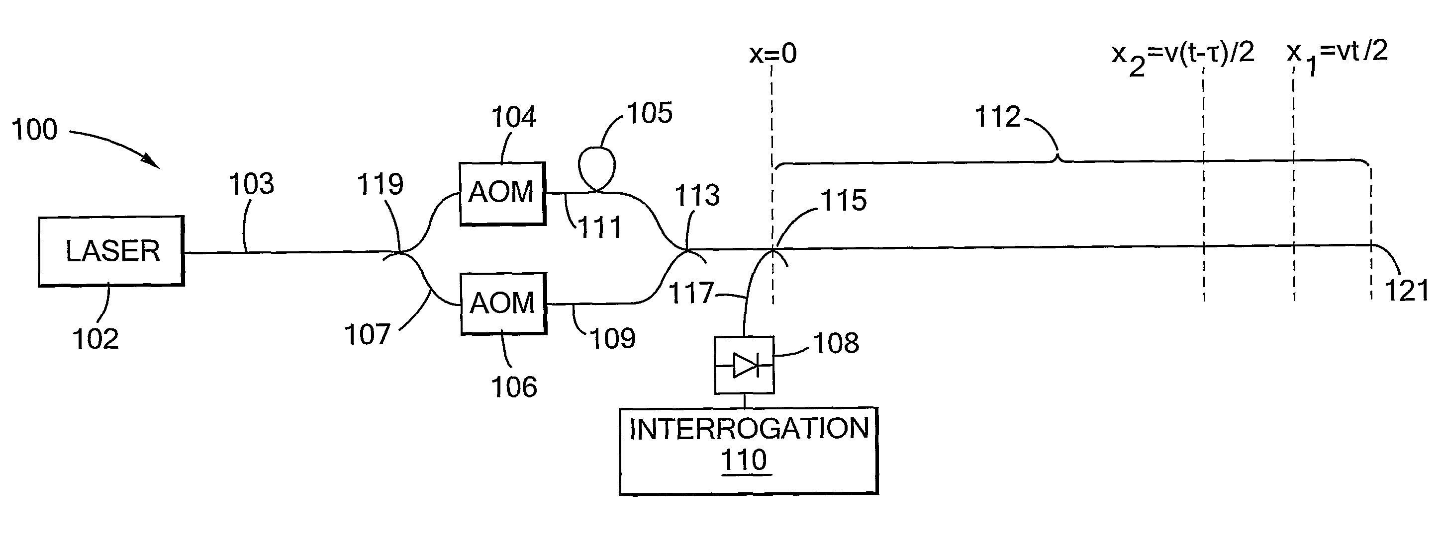
[0036]In FIG. 1, first example traffic sensing and monitoring apparatus of the invention, indicated generally by 100, comprises a cw laser 102, acousto-optic modulators (AOMs) 104, 106, an optical fibre 111 having a sensing portion 112 with proximal 115 and distal 121 ends, a photodetector 108 (e.g. a photodiode) and an interrogation system 110 arranged to obtain samples of the photodetector output signal, and to process the samples to produce an output signal. The optical output of laser 102 is coupled to an optical fibre 103. An optical fibre 107 is coupled to the fibre 103 by a coupler 119. Fibres 103, 107 are input to AOMs 104, 106 respectively. Outputs of the AOMs 104, 106 are coupled into optical fibres 111, 109 respectively, and fibre 109 is coupled to fibre 111 at a position 113. The optical path length between AOM 104 and the position 113 is greater than that between AOM 106 and position 113 due to a 24 m delay loop 105 of fibre 111. A sensing portion 112 of fibre 111 has a...


PUM


Abstract

Traffic sensing and monitoring apparatus (100) comprises a length of optical fiber (112), means (102, 103, 104, 106, 107, 109, 119) arranged to introduce a series of pulse pairs into an input end of the length, each of the pulse pairs comprising first and second pulses of radiation having a frequency difference Ω and the second pulse being delayed with respect to the first by a delay τ, and the apparatus further comprising a photodetector arranged to detect radiation which is Rayleigh-backscattered within the length of fiber towards the input end to generate an output signal in response thereto. Apparatus of the invention allows sensing and monitoring of traffic at any position along a long length of road (e.g. 5 km) with lower installation and maintenance costs per unit length compared to prior art systems providing the same spatial resolution.

Description

BACKGROUND OF THE INVENTION[0001](1) Field of the Invention[0002]The present invention relates to apparatus and methods for sensing and monitoring traffic, particularly, although not exclusively, road-traffic. For example, the invention may also be applied to the sensing and monitoring of rail traffic or aircraft on runways.[0003](2) Description of the Art[0004]The ability to sense and monitor motor vehicles on a length of road or a length of a lane of a multi-lane highway is useful as it allows detection of congested portions of road. Such detection allows drivers to be given advance warning of such portions, preventing further traffic build-up. If the sensing and monitoring is sufficiently detailed, such detection also allows authorities to make appropriate use of available road resources. For example, when lanes of a portion of motorway become congested, the hard-shoulder may be made available for ordinary use by motorists. In the long-term, detailed information on traffic densit...

Claims


Application Information

Patent Timeline
IPC IPC(8): G01J1/04G01D5/353G08G1/02
CPCG01D5/35361G08G1/02E01F11/00G08G1/01G08G1/04
Inventor CRICKMORE, ROGER IANHILL, DAVID JOHN
Owner OPTASENSE HLDG LTD
Why Eureka
Try Eureka