Hybrid power cell

a hybrid power cell and power converter technology, applied in the field of hybrid power cells, can solve the problems of no feedback on the ability to work, the size and weight of the system, and the cost remains higher than the standard silicon power modules, so as to improve the reliability and the size of the power converter, reduce the audible noise, and improve the thermal cycle.

Pending Publication Date: 2021-04-15
FORSEE POWER
View PDF9 Cites 0 Cited by
  • Summary
  • Abstract
  • Description
  • Claims
  • Application Information

AI Technical Summary

Benefits of technology

[0027]Thus, this arrangement reduces the audible noise.
[0028]According to an embodiment, said at least one primary switching unit (131, 135) may be a Gate Turn-OFF thyristor, Insulated-Gate Bipolar Transistor, Field Effect Transistor and / or Metal-Oxide-Semiconductor Field-Effect Transistor and / or said at least one secondary switching unit (171, 175) may be a Field Effect Transistor and / or a Metal-Oxide-Semiconductor Field-Effect Transistor.
[0029]Thus, this arrangement linked of the thermal resistance losses and improves the lifetime, the thermal cycle, the reliability and the size of the power converter (100).

Problems solved by technology

This involves a consequence on the size and the weight of the systems.
However, these components are new on the market and there are no feedbacks on their ability to work under a large temperature range over a long time period especially in the applications in which there are thermal cycling constraints.
Moreover, their cost remains higher than the standard Silicon power modules.
Those thermal stresses are due to the quick charges from the kinetic energy recovery, during braking phase, due to the high sourcing inrush current required by the traction units, and / or due to the low power consumption from the Heating Ventilation Air Conditioning for instance.
On top of that, in public transport system particularly, the quick recharges of the ESEs occur during brief stops when the passengers go up and down which can generate a high audible noise due to the magnetrostriction effect of the magnetic elements and may annoy the passengers.
In several soft switching power converters, it is often impossible to work without any loads because the snubber capacitors are fast discharged through the power semiconductors.
This loss reduces the lifetime of the system.

Method used


Image

  • Hybrid power cell
  • Hybrid power cell
  • Hybrid power cell

Examples


Embodiment Construction

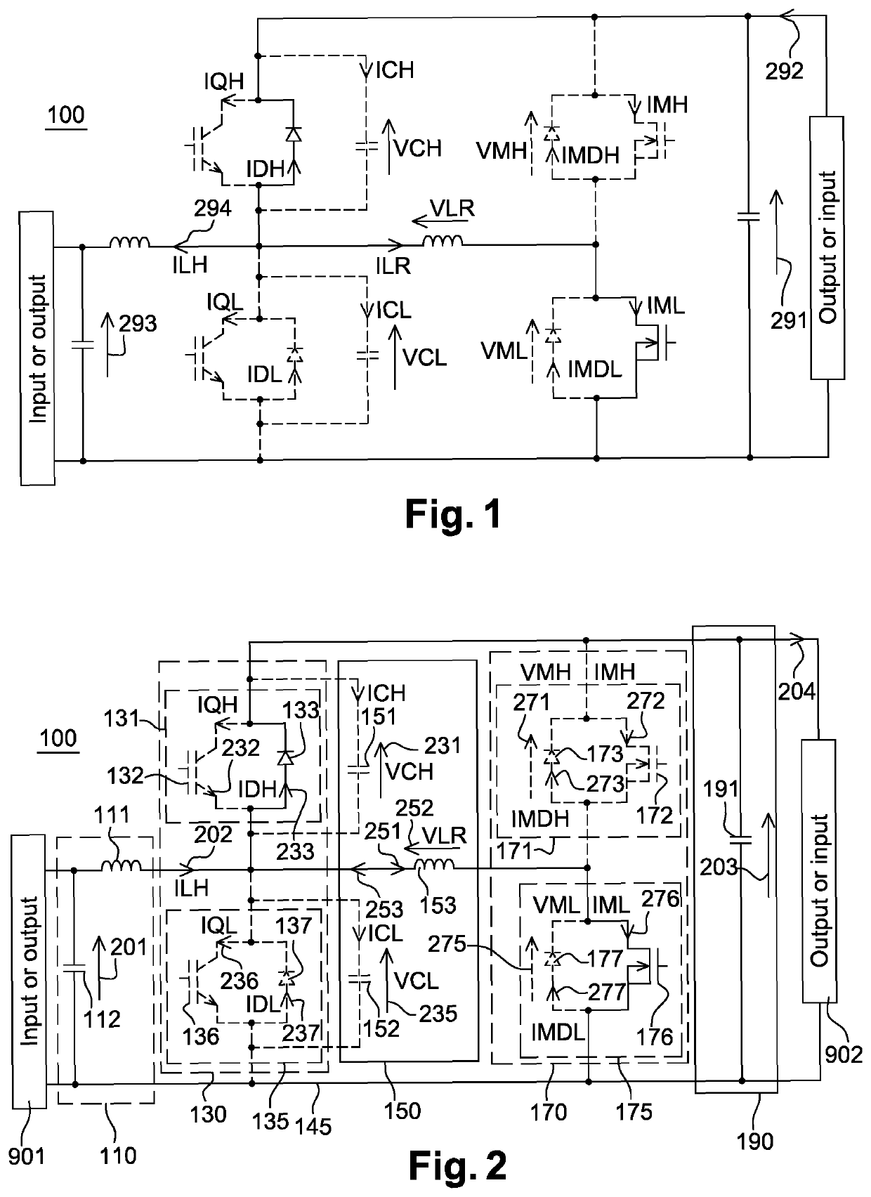
[0138]The present invention may provide a power converter 100 with an improved lifetime, and reliability while reducing the size and the audible noise. The power converter 100 of the present invention, as depicted on FIGS. 1 and 2, may be deemed to improve the lifetime of Energy Storage Systems, ESS for short, also known as Energy Storage Elements, ESE for short, by minimizing current flowing through them. The power converter 100 described in this present application may be dedicated to energy storage systems having a high nominal voltage, which may mean comprised between 750 VDC and 950 VDC. In particular, the present invention may provide a bi-directional power converter 100 since the power converter 100 may function as a boost converter 100 or a buck converter 100.

[0139]This power converter 100 may include at least one primary switching arrangement 130, secondary switching arrangement 170 and a resonant unit 150 connecting the primary switching arrangement 130 and the secondary s...


PUM


Abstract

The present invention relates to a bi-directional power converter (100) for converting an input voltage into an output voltage. The bi-directional power converter (100) may comprise a primary switching unit having a primary switching frequency and a secondary switching unit having a secondary switching frequency: the primary switching frequency being lower than the secondary switching frequency.

Description

TECHNICAL FIELD OF THE INVENTION[0001]The present invention relates to a power converter for converting an input power into an output power, a boost process and / or a buck process for converting an input power into an output power. More particularly, the present invention is dedicated, but not exclusively, to electrical traction systems able to drive electrical motors and to recover kinetic energy towards the embedded Energy Storage Systems.STATE OF THE ART[0002]As the technologies of batteries and supercapacitors were improved over the last decades, electric vehicles have become an attractive solution with an economic reality. Moreover, due to the commitment of several countries around the world to respect the COP21 act, traditional full gasoline vehicle may be abandoned replacing by electrical solution. One of the first application will be the public transport like bus and tramway systems for example. In these applications, high power is required to supply the traction units.[0003]...

Claims


Application Information

Patent Timeline
Patent Type & Authority Applications(United States)
IPC IPC(8): H02M3/158H02M1/088
CPCH02M3/1582H02M2001/0054H02M1/088H02M3/158Y02B70/10H02M1/0058H02M7/4811H02M1/0054
Inventor PERON, BENOÎT
Owner FORSEE POWER
Why Eureka
Try Eureka