Method of controlling a three-phase permanent magnet synchronous motor for reducing acoustic noise

a synchronous motor and three-phase technology, applied in the direction of torque ripple control, dynamo-electric machines, synchronous motor starters, etc., can solve the problem of hardly meeting the requirement of a relatively large current bandwidth, and achieve the effect of greatly reducing the noise of torque rippl

Active Publication Date: 2014-08-26
STMICROELECTRONICS SRL
View PDF16 Cites 10 Cited by
  • Summary
  • Abstract
  • Description
  • Claims
  • Application Information

AI Technical Summary

Benefits of technology

[0013]According to an embodiment of the motor drive circuit, audible noise due to torque ripple is greatly reduced, and may be practically deleted, by injecting additional components adapted to compensate the effects on the produced torque which are due to 5th and 7th harmonics of BEMF. According to another embodiment, this may be accomplished by injecting additional components at the sixth harmonic of the stator electrical frequency, the fundamental or main frequency hereafter, such that the fifth and seventh harmonics of the torque ripple are compensated.

Problems solved by technology

The requirement of a relatively large current bandwidth is hardly satisfied when stator currents feedback signals come from low cost devices, such as shunt resistors placed on the DC bus link or below the low-side switch of the driving inverter legs.

Method used


Image

  • Method of controlling a three-phase permanent magnet synchronous motor for reducing acoustic noise
  • Method of controlling a three-phase permanent magnet synchronous motor for reducing acoustic noise
  • Method of controlling a three-phase permanent magnet synchronous motor for reducing acoustic noise

Examples


Embodiment Construction

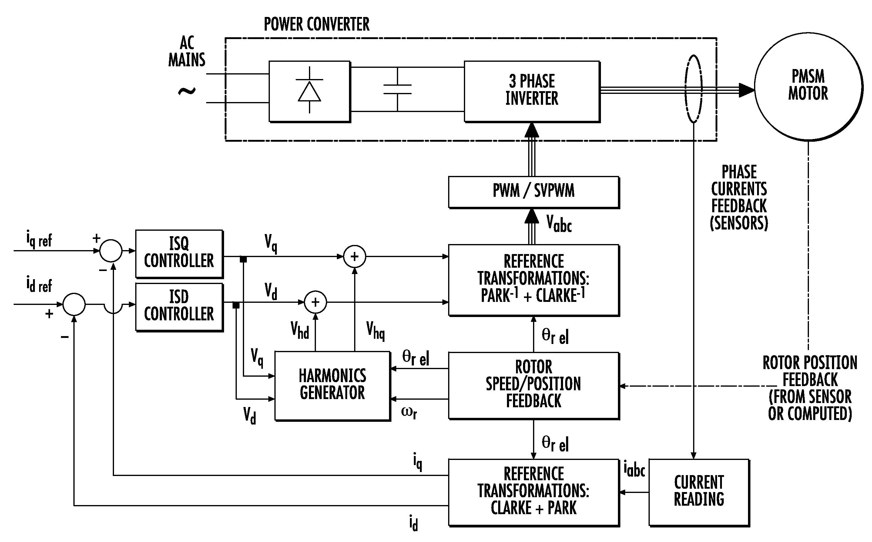
[0018]Acoustic noise generated by driving an electric motor with sinusoidal driving voltages is effectively reduced by injecting harmonics at a frequency multiple of the stator electrical frequency (called main harmonic hereafter) to compensate the fifth and seventh harmonic of the BEMF.

[0019]According to an embodiment of the control method, schematically illustrated in FIG. 3, the additional components at higher harmonics are injected downstream the ISD and ISQ controllers by a dedicated generator harmonics generator (e.g., a first compensation circuit as illustrated in FIGS. 3 and 4) and are added to the quadrature and direct components of the control voltages Vsq and Vsd, respectively. This compensates higher order harmonics of the BEMF induced in the windings by the motion of the rotor. According to another embodiment, the additional components (e.g., via a second compensation circuit, which may include adders as illustrated in FIGS. 3 and 4) at the sixth harmonic compensate the...


PUM


Abstract

A method of controlling a synchronous motor that may include windings and a power driving stage coupled to the windings, may include using a feedback loop including using a feedback circuit coupled to the windings to generate current feedback components, using current controllers for generating respective voltage signals, and using an anti-transform circuit for generating control signals for the power driving stage. Using the feedback loop may include generating additional compensation signals for compensating the control signals, and adding the additional compensation signals from the current controllers by one of generating the additional compensation signals as quadrature and direct voltage compensation signals and adding them to the voltage signals to generate compensated quadrature and direct signals, and supplying the compensated quadrature and direct signals to the power driving stage by providing the compensated quadrature and direct signals to the anti-transform circuit.

Description

FIELD OF THE INVENTION[0001]This invention relates to current vector control of multi-phase electrical motors, and, more particularly, to a method and a related device for driving a three-phase permanent magnet synchronous motor (PMSM) while reducing acoustic noise.BACKGROUND OF THE INVENTION[0002]One of the most widely used techniques for controlling PMSMs is vector control, or its field oriented control (FOC) embodiment. This technique, which also uses the space vector modulation (SVM) technique, may be able to produce a stator magnetic flux, synchronous with the rotor flux, whose amplitude and related displacement (orientation) increase the electromagnetic torque produced versus current consumption. Improved accuracy measurement of the rotor position, and speed and phase currents of the motor may be desired.[0003]FIG. 1 is a block diagram of a system for controlling the torque in a three-phase motor using the FOC technique. The feedback signals, Isd (direct current) and Isq (quad...

Claims


Application Information

Patent Timeline
Patent Type & Authority Patents(United States)
IPC IPC(8): H02P21/00
CPCH02P29/0038H02P29/50
Inventor COSTANZO, DINOBILLE, STELLO MATTEO
Owner STMICROELECTRONICS SRL
Why Eureka
Try Eureka