Converting circuit and controller for controlling the same

a technology of controller and conversion circuit, which is applied in the direction of dc-dc conversion, power conversion system, instruments, etc., can solve the problems of raised audible noise, reduce the switching loss, reduce the amount of switching of transistors, and reduce the effect of audible nois

Active Publication Date: 2012-08-28
GREEN SOLUTION TECH CO LTD
View PDF19 Cites 15 Cited by
  • Summary
  • Abstract
  • Description
  • Claims
  • Application Information

AI Technical Summary

Benefits of technology

[0009]Although the DC-DC buck converter of the conventional arts is able to decrease amount of switching of the transistors to lower switching loss, but the problem of audible noise raised. The present invention provides a converting circuit for reducing audible noise and a controller for controlling the same, which use a discharging path to discharge the stored energy of the converting circuit, and so the converting circuit and the controller can be forced to operate at a frequency beside the human hearing range of 20 Hz to 20 kHz for avoiding the audible noise.
[0012]The present invention also provides a method for reducing audible noise of a converting circuit. The method comprises the steps of: (a) determining a discharging resistance value according to a predetermined output voltage, a predetermined period, and a minimum energy transmitted by a converting module in an operating period, wherein the converting module is controlled by a controlling signal of a controller; and (b) coupling a discharging circuit to a capacitance unit of the converting module, wherein a resistance value of the discharging circuit is determined according to the discharging resistance value and thereby a time interval of the generated controlling signals is short than or equal to the predetermined period.

Problems solved by technology

Although the DC-DC buck converter of the conventional arts is able to decrease amount of switching of the transistors to lower switching loss, but the problem of audible noise raised.

Method used


Image

  • Converting circuit and controller for controlling the same
  • Converting circuit and controller for controlling the same
  • Converting circuit and controller for controlling the same

Examples


Embodiment Construction

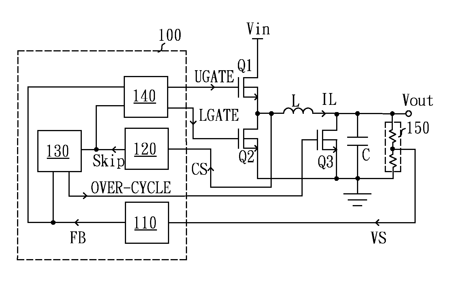
[0029]The spirit of the present invention is to use a discharging path to maintain the lowest switching frequency of switching unit in a converting module than the human hearing range for avoiding the audible noise. The discharging path is a continuously discharging path or a controlled discharging path.

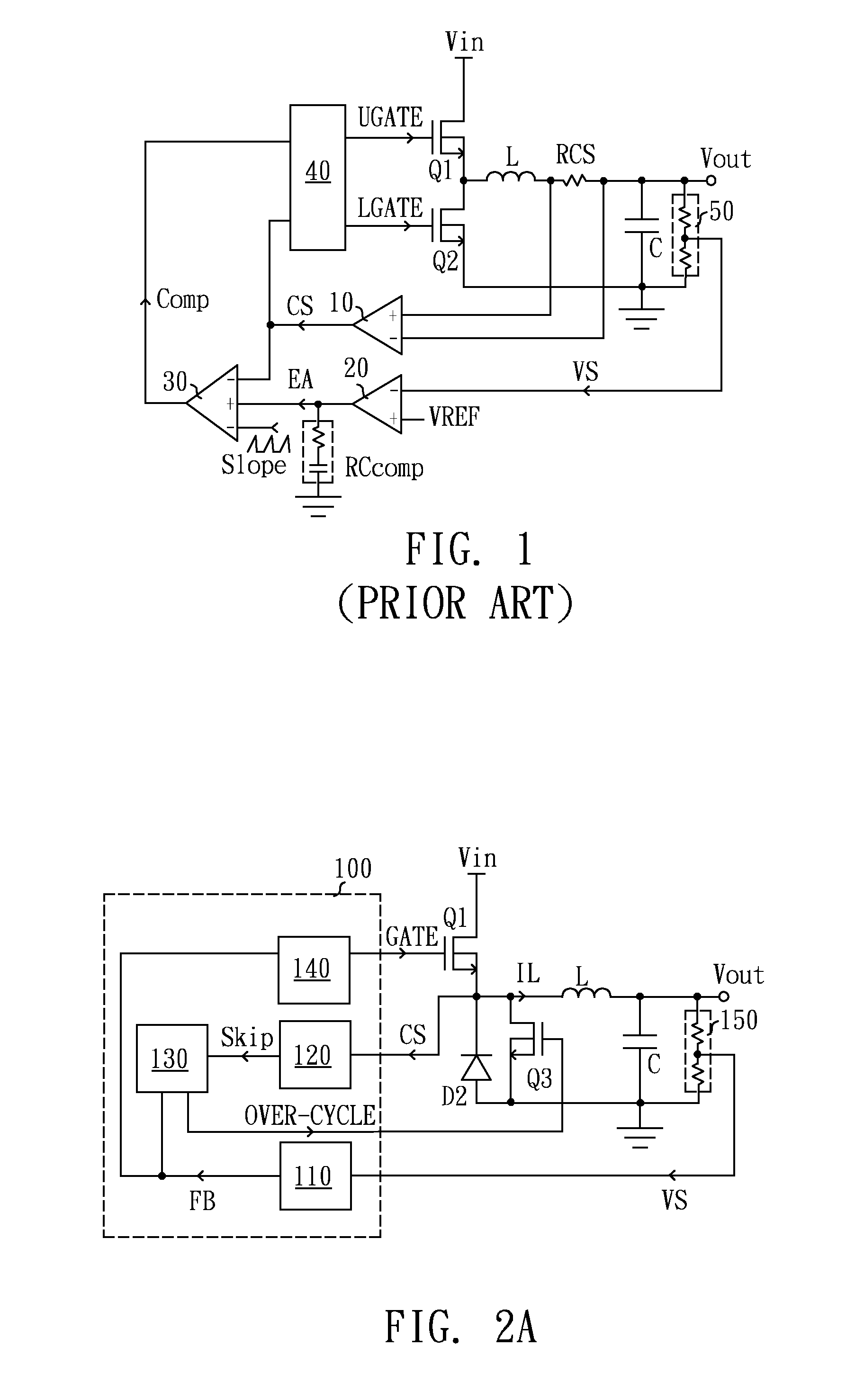
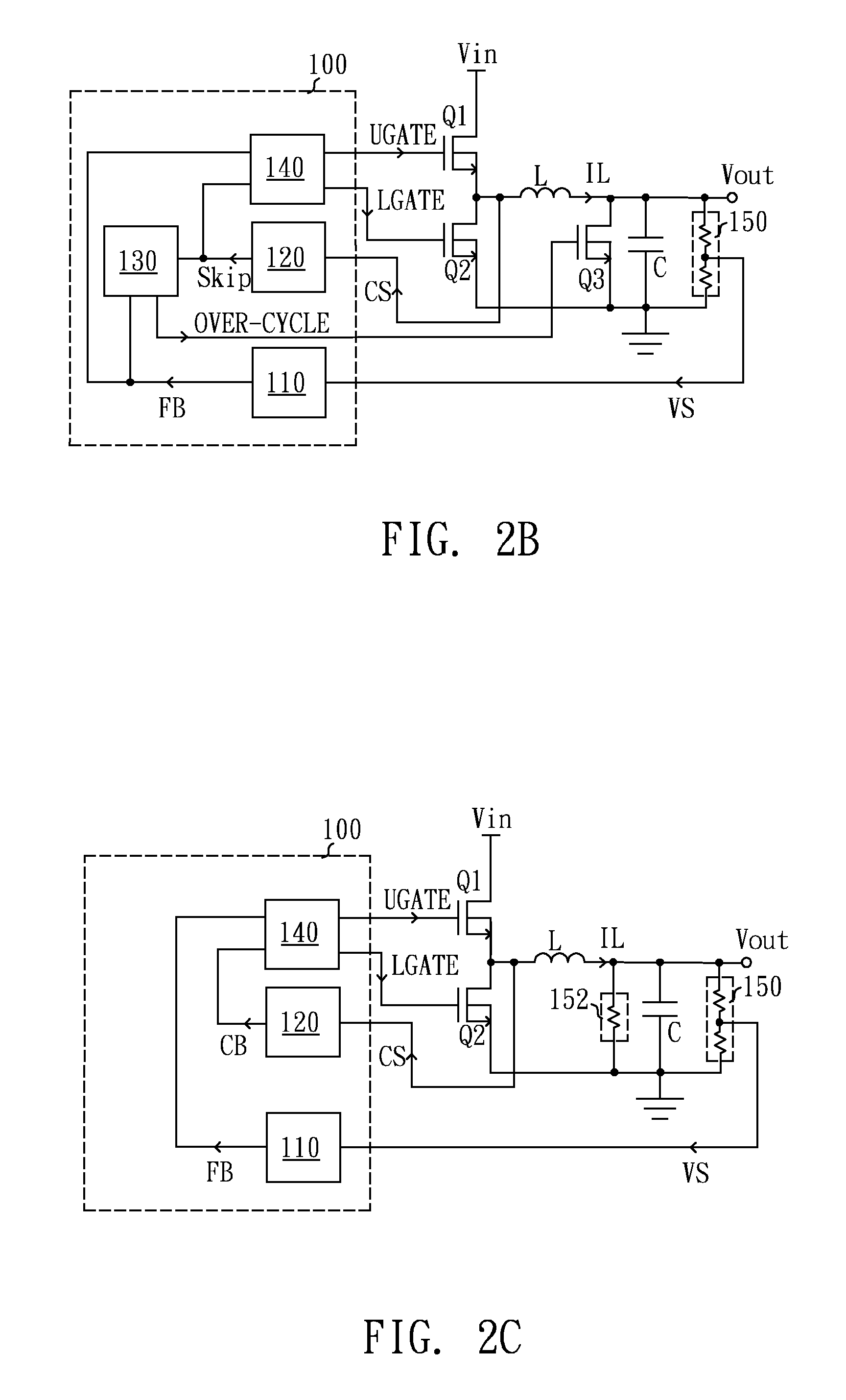
[0030]Please refer to FIG. 2A, it is a schematic block diagram of a DC-DC converting circuit for reducing audible noise in a preferred embodiment according to the present invention. The DC-DC converting circuit, which is used to convert an input voltage Vin into an output voltage Vout, comprises a converting module, a noise avoiding unit Q3, and a controller 100. The converting module comprises a first switching unit Q1, a synchronous diode D2, an inductor L as an energy storage unit, a capacitor C, and a voltage detector 150. The controller 100 comprises a first detecting unit 110, a second detecting unit 120, a period judging unit 130, and a driving unit 140. The controller 100 rec...


PUM


Abstract

The present invention uses a discharge path to release the power stored in an output capacitor of a converting circuit when the time interval between two adjacent switching thereof is too long and may generate noises whose frequencies can be sensed by human ears. Hence, the present invention can keep the operating frequency of the converting circuit higher than a predetermined frequency and reduce the audio noise of the converting circuit.

Description

CROSS-REFERENCE TO RELATED APPLICATION[0001]This application claims the priority benefits of Taiwan patent application serial no. 97148845, filed on Dec. 16, 2008, and application serial no. 98101963, filed on Jan. 20, 2009. The entirety of each of the above-mentioned patent applications is hereby incorporated by reference herein and made a part of specification.BACKGROUND OF THE INVENTION[0002](1) Field of the Invention[0003]The present invention relates to a converting circuit and a controller for controlling the same, and more particularly to a converting circuit for reducing audible noise and a controller for controlling the same.[0004](2) Description of the Prior Art[0005]FIG. 1 is a schematic circuit diagram of a DC-DC buck converter in the conventional arts, which is utilized for converting a DC input voltage Vin into a DC output voltage Vout. The DC-DC buck converter has a first switch Q1, a second switch Q2, an inductor L, a capacitor C, a voltage detector 50, a current det...

Claims


Application Information

Patent Timeline
Patent Type & Authority Patents(United States)
IPC IPC(8): G05F1/44
CPCH02M3/158H02M2001/322H02M1/44H02M1/322
Inventor CHEN, JI-MINGYU, CHUNG-CHE
Owner GREEN SOLUTION TECH CO LTD
Why Eureka
Try Eureka