Switching power supply device and the semiconductor integrated circuit for power supply control

a technology of power supply device and integrated circuit, which is applied in the direction of electric variable regulation, process and machine control, instruments, etc., can solve the problems of increasing switching loss, heat release value, and failure to miniaturize, and achieve the effect of reducing switching loss

Inactive Publication Date: 2007-01-02
RENESAS TECH CORP
View PDF7 Cites 58 Cited by
  • Summary
  • Abstract
  • Description
  • Claims
  • Application Information

AI Technical Summary

Benefits of technology

[0022]According to the above-mentioned means, an on / off control signal is generated before zeroing a source-drain voltage of the transistor in the switching circuit even if there is a delay in operations of the switching circuit at the primary side. The transistor in the switching circuit turns on or off simultaneously with setting the source-drain voltage to 0 V. It is possible to decrease switching losses at the primary side.

Problems solved by technology

However, increasing the switching frequency also increases switching losses and the heat release value.
This necessitates a radiator plate and the like, resulting in unsuccessful miniaturization.

Method used


Image

  • Switching power supply device and the semiconductor integrated circuit for power supply control
  • Switching power supply device and the semiconductor integrated circuit for power supply control
  • Switching power supply device and the semiconductor integrated circuit for power supply control

Examples


first embodiment

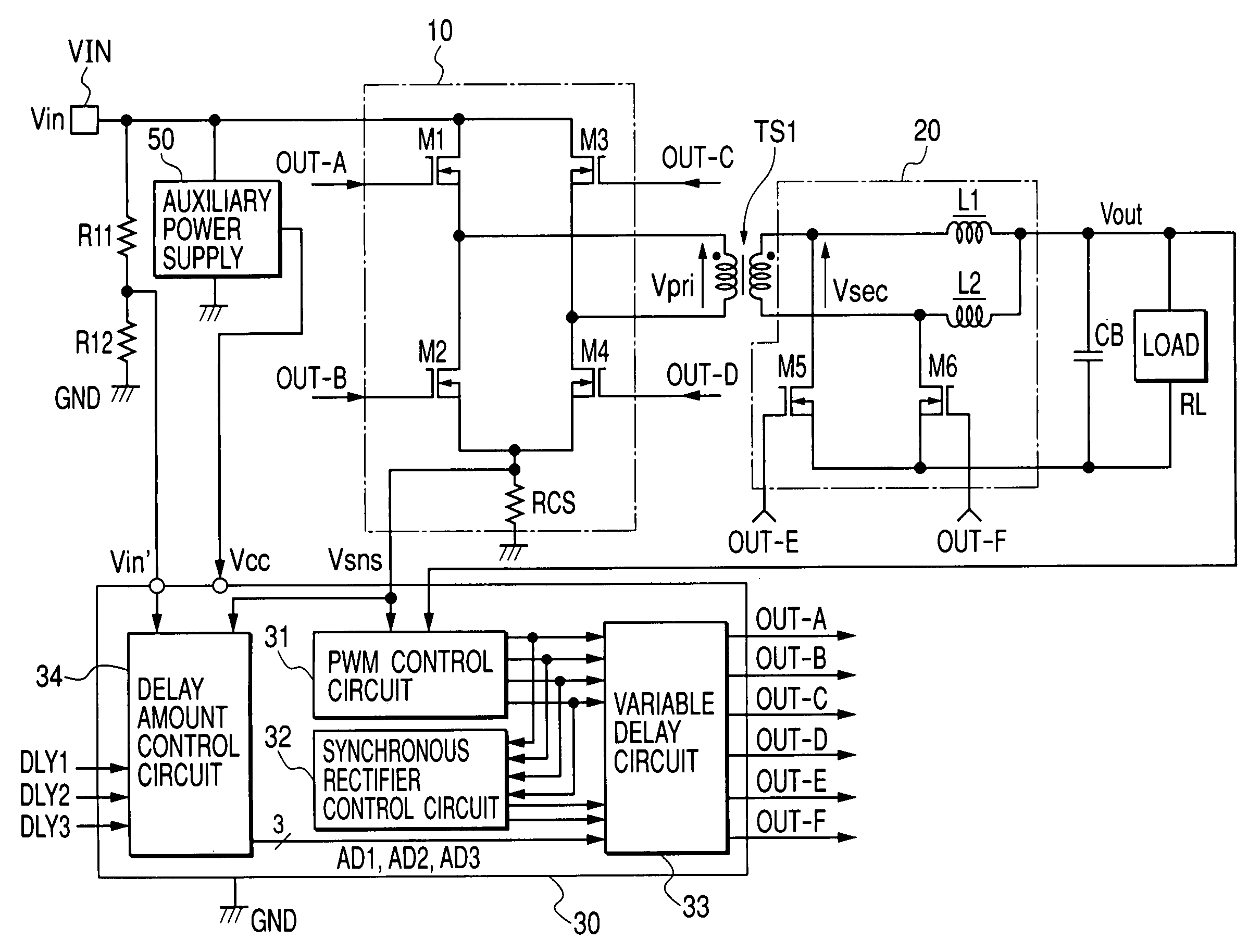
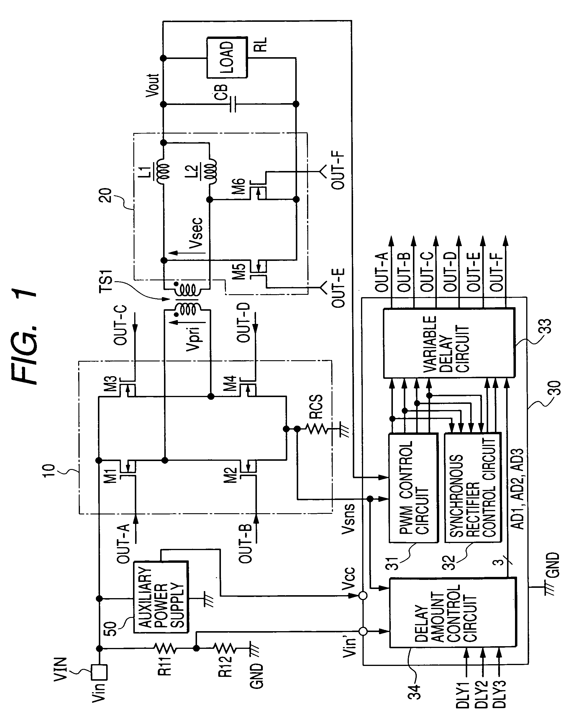
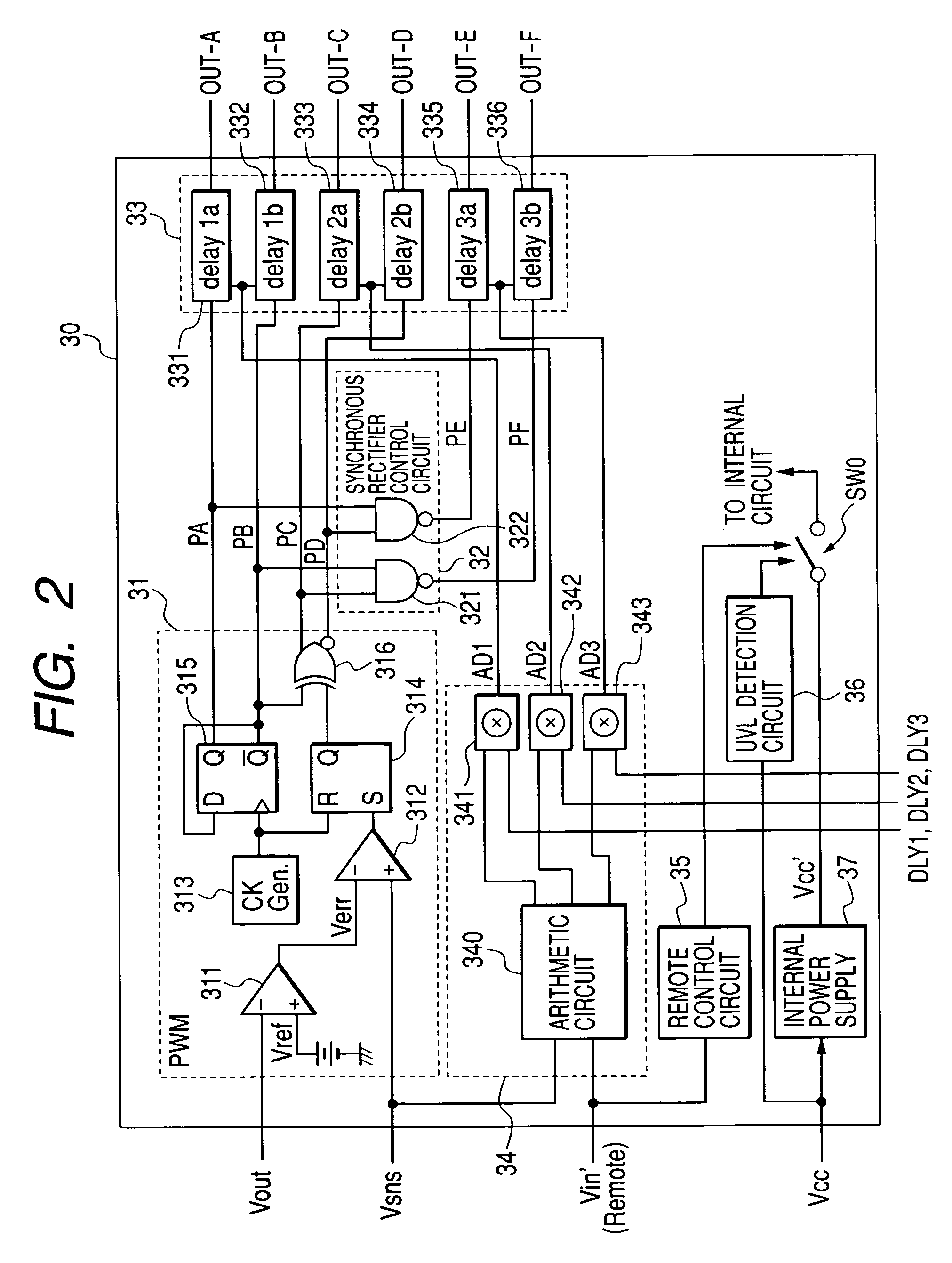
[0042]FIG. 1 shows a DC-DC converter according to the present invention. In FIG. 1, the reference symbol TS1 represents a transformer for voltage conversion. The reference numeral 10 represents a switching circuit to drive a primary coil of the transformer TS1 with alternate currents. The reference numeral 20 represents a full-wave rectifier circuit to rectify an AC voltage induced by the secondary coil of the transformer TS1 and convert the voltage into a DC voltage. The reference numeral 30 represents an integrated control circuit (hereafter referred to as a power control IC) to control to drive switch MOSFETs M1 through M4 constituting the above-mentioned switching circuit 10 and synchronous rectification MOSFETs M5 and M6 constituting the rectifier circuit 20. The reference numeral 50 represents an auxiliary power circuit such as a switching regulator that is supplied with 48 V input DC voltage Vin and generates to supply DC power voltage Vcc such as 12 V needed for the power co...

second embodiment

[0100]The following describes the DC-DC converter according to the present invention with reference to FIG. 15. The mutually corresponding elements and circuits in FIGS. 15 and 1 are designated by the same reference numerals and a duplicate description is omitted for simplicity.

[0101]Instead of the delay amount control circuit 34 in the previous embodiment, the embodiment in FIG. 15 provides input terminals P11 and P12, a 0 V decision circuit 41, an external terminal P13, and difference circuits 42a and 42b. The input terminal P11 and P12 monitor the terminal voltages V11 and V12 of the primary coil in the switching circuit 10. The 0 V decision circuit 41 comprises comparators CMP1 through CMP4. The external terminal P13 supplies voltage VBS used as a criterion. The difference circuits 42a and 42b generate differences between the voltage Vin′ proportional to the input voltage Vin divided by the resistors R11 and R12 and the coil's terminal voltages V11 and V12, respectively.

[0102]Ac...


PUM


Abstract

It is aimed at decreasing losses not only in a synchronous rectifier circuit provided at a secondary side of a DC-DC converter, but also in a full-bridge switching circuit provided at a primary side thereof. The DC-DC converter comprises a transformer for voltage conversion, a synchronous rectifier circuit at the secondary side, and a full-bridge switching circuit at the primary side. The DC-DC converter performs synchronous rectifier control which uses switch transistors to change paths of currents flowing through the secondary coil in synchronization with switching operations at the primary side. The DC-DC converter detects currents flowing through a load at the secondary side, primary-side currents varying with the load currents, or primary-side input voltages to dynamically control off-timings of a synchronous rectification transistor at the secondary side. In addition, the DC-DC converter detects primary-side input voltages and currents flowing through the secondary-side load to dynamically control on-timings of a transistor in the primary-side switching circuit.

Description

BACKGROUND OF THE INVENTION[0001]The present invention relates to a technology for decreasing losses in a switching power supply device having a transformer for voltage conversion. More specifically, the present invention relates to a technology effectively used for DC-DC converters (power supply devices of direct current to direct current power converter type) having a synchronous rectifier circuit at the transformer's secondary side.[0002]Conventionally, there is known a DC-DC converter as shown in FIG. 17. Such DC-DC converter uses a full-bridge switching circuit for the primary circuit and a synchronous rectifier circuit for the secondary rectifier circuit.[0003]The DC-DC converter in FIG. 17 is a switching power circuit having the following configuration. The full-bridge switching circuit comprises switches SA through SD and drives a primary coil of a transformer TS1 with alternate currents. Synchronous rectification switches SE and SF are used to rectify alternate voltages ind...

Claims


Application Information

Patent Timeline
Patent Type & Authority Patents(United States)
IPC IPC(8): H02M3/335H02M7/21H02M3/28H02M3/337
CPCH02M3/33592H02M3/3376Y02B70/1491Y02B70/1475H02M2001/0048H02M1/0048Y02B70/10
Inventor HOSOKAWA, KYOICHIONDA, KENICHIUEHARA, YOICHIKUDO, RYOTAROYOSHIDA, SHINICHI
Owner RENESAS TECH CORP
Why Eureka
Try Eureka