Submodule topology for modular multi-level transverter and application of modular multi-level transverter

A modular multi-level, sub-module technology, applied in the conversion equipment for intermediate conversion to DC, irreversible DC power input conversion to AC power output, DC power input conversion to DC power output, etc., can solve the problem Problems such as increasing sub-modules, large capacitor voltage, increasing sub-module manufacturing costs and difficulty in process design, etc., to achieve the effect of reducing the number

Active Publication Date: 2014-09-17
HUAZHONG UNIV OF SCI & TECH
View PDF4 Cites 61 Cited by
  • Summary
  • Abstract
  • Description
  • Claims
  • Application Information

AI Technical Summary

Problems solved by technology

However, after a fault occurs on the DC side of this hybrid converter, the clamped twin sub-module capacitors will always be charged, resulting in excessive capacitor voltage. A damping resistor must be added to the clamped twin sub-modules to dissipate the excess Energy, additional damping resistance will increase the size of the sub-module, heat sink, weight, etc., thereby increasing the manufacturing cost and process design difficulty of the sub-module, and increasing the cost of the sub-module

Method used


Image

  • Submodule topology for modular multi-level transverter and application of modular multi-level transverter
  • Submodule topology for modular multi-level transverter and application of modular multi-level transverter
  • Submodule topology for modular multi-level transverter and application of modular multi-level transverter

Examples


Embodiment Construction

[0067] In order to make the object, technical solution and advantages of the present invention more clear, the present invention will be further described in detail below in conjunction with the accompanying drawings and embodiments. It should be understood that the specific embodiments described here are only used to explain the present invention, not to limit the present invention. In addition, the technical features involved in the various embodiments of the present invention described below can be combined with each other as long as they do not constitute a conflict with each other.

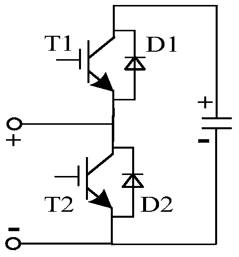
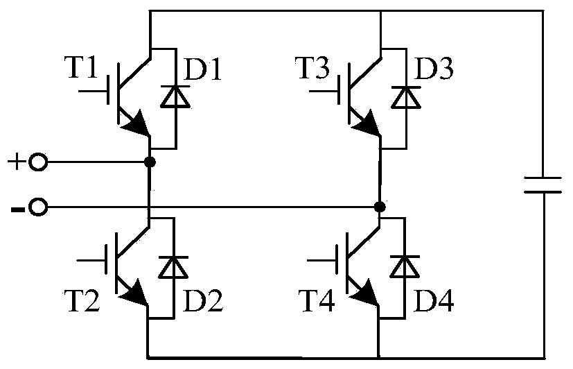
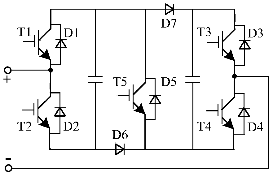
[0068]The new sub-module topology provided by the embodiment of the present invention is mainly used to construct a new modular multilevel converter, so that the new modular multilevel converter is used in two-terminal DC power transmission, multi-terminal DC power transmission and DC power grid, and its significant The technical performance is that compared with the conventional half-bridge ...


PUM


Abstract

The invention discloses a submodule topology for a modular multi-level transverter. The submodule topology comprises a first switching module, a second switching module, a direct current capacitor and a third switching module, wherein the first switching module and the second switching module are connected in series, the negative end of the first switching module is connected with the positive end of the second switching module, and the first switching module and the second switching module are formed by connecting full-controlled devices and diodes in an antiparallel mode. The positive electrode and the negative electrode of the direct current capacitor are connected with the positive end of the first switching module and the negative end of the second switching module. The third switching module is electrically connected with the first switching module and the second switching module, so that a full-controlled device of the third switching module applies trigger pulses all the time during normal operation and is in a conducting state all the time, and currents of direct current faults can be blocked by locking the trigger pulses of the third switching module when direct current faults happen. The invention further comprises the transverter comprising a submodule and application of the transverter. By means of the submodule topology for the modular multi-level transverter and application of the modular multi-level transverter, a function of isolating the direct current faults is achieved, quantity and switching losses of switching devices in the submodule are decreased, and requirements on trigger simultaneity are reduced.

Description

technical field [0001] The invention belongs to the technical field of power system transmission and distribution, and more specifically relates to a novel sub-module topology of a modular multilevel converter and a hybrid converter composed of a novel sub-module topology and a half-bridge sub-module topology topology. Background technique [0002] At present, high-voltage direct current transmission (HVDC) technology has been widely used in the field of renewable energy grid integration. With the further development of high-voltage direct current transmission technology, multi-terminal direct current transmission (MTDC) technology and direct current grid technology that can realize multi-source power supply and multi-drop power receiving have received strong attention. [0003] Whether it is two-terminal HVDC transmission technology, or multi-terminal HVDC transmission technology and DC grid technology, converter technology is one of its key technologies. The inverter con...

Claims


Application Information

Patent Timeline
Patent Type & Authority Applications(China)
IPC IPC(8): H02H7/10H02M3/137
CPCH02M7/49H02M7/537H02M1/32H02M7/483H02M7/4835H02M5/44
Inventor 林卫星向往文劲宇
Owner HUAZHONG UNIV OF SCI & TECH
Why Eureka
Try Eureka