Apparatus for controlling three-phase AC motor on two-phase modulation technique

a technology of alternating current and three-phase ac, which is applied in the direction of electronic commutation motor control, motor/generator/converter stopper, dynamo-electric converter control, etc., can solve the problems of insufficient “2/3-fixing type” and insufficient control of the two-phase modulation operation of the motor, and achieve the effect of reducing the switching loss

Active Publication Date: 2005-09-08
DENSO CORP
View PDF13 Cites 58 Cited by
  • Summary
  • Abstract
  • Description
  • Claims
  • Application Information

AI Technical Summary

Benefits of technology

[0014] In light of the above-described problems, an object of the present invention is to provide a motor control apparatus that is able to operate a three-phase AC motor, with avoiding, in a greater or less degree, the fixed phases from being switched in a deteriorated condition, while still reducing the switching loss caused in an inverter for PWM control incorporated in the apparatus.

Problems solved by technology

In various applications of electronic motors, a higher need for reducing loss caused in the motors has arisen, partly due to environmental problems.
In terms of this requirement, the foregoing “2π / 3-fixing type” is insufficient, because the switching loss cannot be suppressed fully in some operation ranges showing higher speeds and larger amounts of torque.
However, it has been pointed out that, when the output voltage is smaller in amplitude, switchover timing for the fixed phases tends to be erroneous, thus failing to keep a well-controlled two-phase-modulation operation of the motor.
In addition, the foregoing switchover between the three-phase modulation drive and the two-phase modulation drive on “2π / 3-fixing type” do not always operate well.
This is attributable to the fact that the three-phase voltages provide time-dependent AC waveforms which are likely to undergo mixing with noise voltage so that precision in switchover timing becomes poor.
In other words, the switchover that relies upon detection of the amplitudes of the three-phase voltages has a difficulty in sufficiently reducing the switching loss.

Method used


Image

  • Apparatus for controlling three-phase AC motor on two-phase modulation technique
  • Apparatus for controlling three-phase AC motor on two-phase modulation technique
  • Apparatus for controlling three-phase AC motor on two-phase modulation technique

Examples


first embodiment

[0047] (First Embodiment)

[0048] Referring to FIGS. 1-10, a first embodiment of a motor control apparatus according to the present invention will now be described.

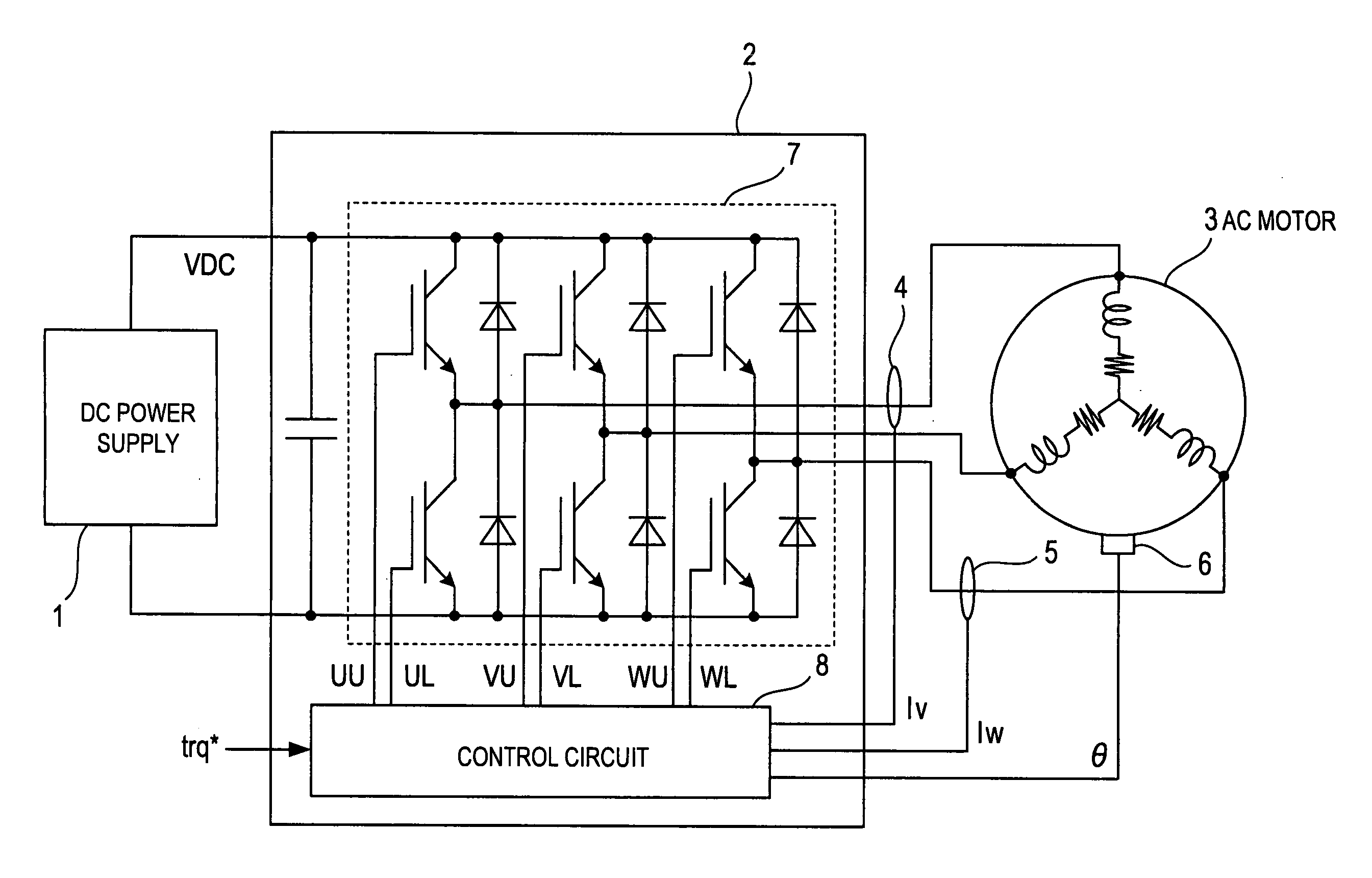
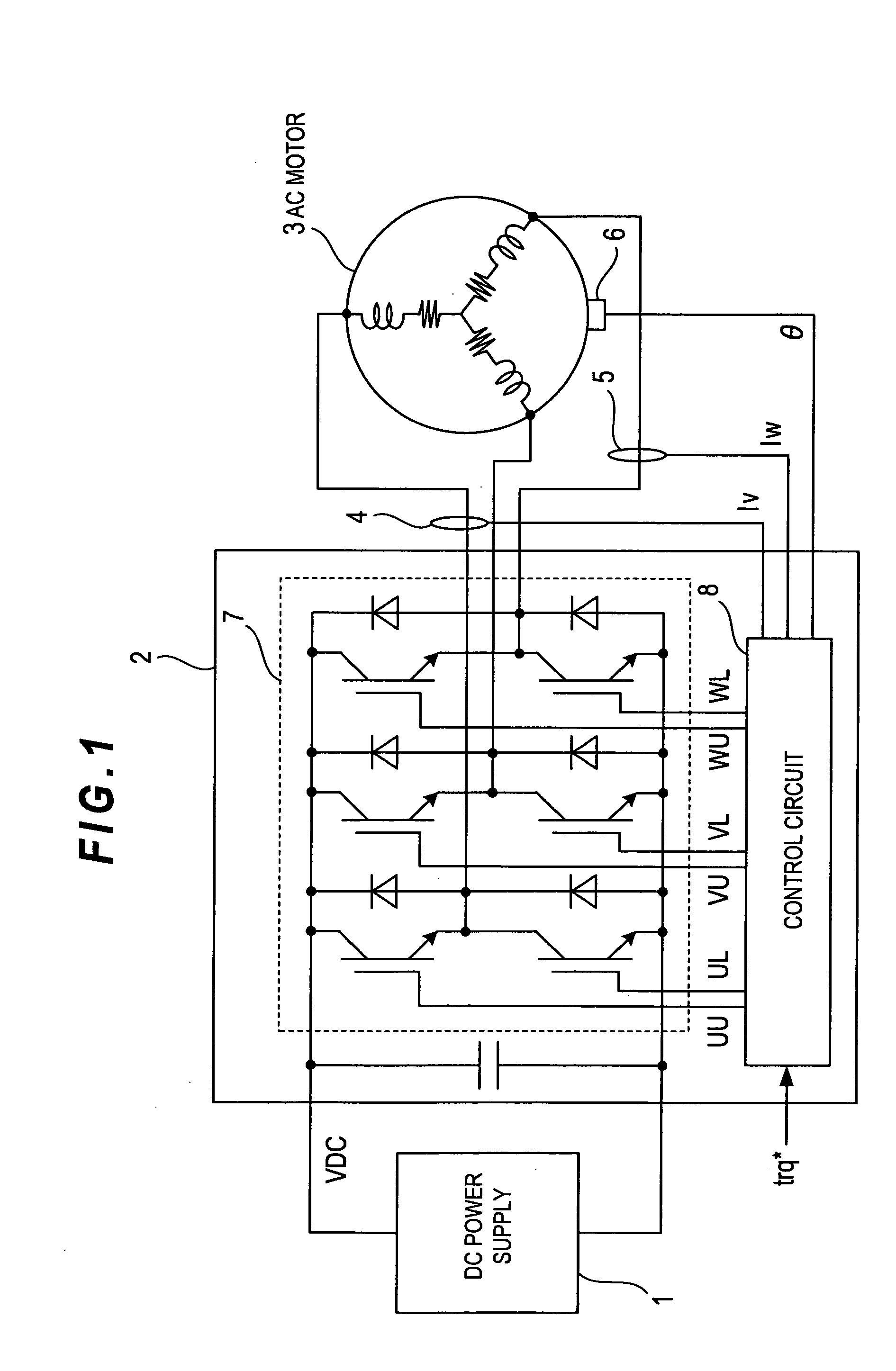
[0049]FIG. 1 outlines the electric configuration of a motor apparatus, which includes the motor control apparatus according to the present embodiment. As shown, the motor apparatus is provided with a DC (direct current) power supply 1, driver 2, and three-phase AC synchronous motor 3, in addition to two current sensors 4 and 5 and motor rotation sensor 6. The motor 3 is for example an on-vehicle motor producing power for running a vehicle such as hybrid car.

[0050] Of these, the current sensors 4 and 5 are in charge of detecting signals indicative of phase currents. The motor-rotation sensor 6 is in charge of detecting a signal to show an electrical angle indicative of the rotation of the motor 3 and which serves as motor rotational position detecting means.

[0051] The driver 2 is equipped with an inverter 7 and a control ...

first modification

[0084] (First Modification)

[0085] A first modification relates to a further control of the inverter 7. To be specific, all the three lower arm elements are switched on, while all the three upper arm elements are switched off. That is, the control circuit 8 is designed to operate on a flowchart roughly shown in FIG. 11, in which the determination whether or not an inverter stop command has been read in is made (step S11). When this determination is YES, the inverter 7 is made to stop operating (step S12). Then all the lower arm elements are switched on and all the upper arm elements are switched off (step 813).

[0086] Accordingly, in the bootstrap circuit shown in FIG. 8, ting on all the lower arm elements 101 enables the voltage VN of the power supply 104 to quickly charge the capacitor 103, the power supply 104 powering the driver circuit for driving the lower arm elements 101 and the capacitor 103 powering the driver circuit 100 for driving the upper arm elements 102. This quick c...

second modification

[0087] (Second Modification)

[0088] A second modification relates to another control of the inverter 7. FIG. 12 outlines a flowchart on which the inverter 7 is controlled by the control circuit 8. Specifically, as shown therein, it is determined whether or not the inverter 7 has been actuated, by detecting an inverter actuation command (step 821). If it is determined YES, all the upper arm elements are switched on and all the lower arm elements are switched off (step S22). This arm element control continues for a predetermined period of time after activating the inverter 7 (step S23).

[0089] This control of the upper and lower arm elements 102 and 101 results in that, for only the predetermined period of time immediately after the activation of the inverter 7, the capacitor 103 is charged. Like the first modification, in the bootstrap circuit shown in FIG. 8, turning on all the lower arm elements 101 enables the voltage VN of the power supply 104 to quickly charge the capacitor 103. ...


PUM


Abstract

An apparatus is provided to control a three-phase AC motor and comprises an inverter and a controller. The inverter powers the motor in response to a three-phase PWM command. The control circuit controls the inverter based on two modulation techniques selectively switched from one the other depending on information indicative of an operation state of the motor. One modulation technique gives the PWM command a first two-phase modulation allowing each phase voltage to be fixed at a predetermined voltage level in turn at intervals of an electrical angle of 2π/3. The other modulation technique gives the PWM command a second two-phase modulation allowing each phase voltage to be fixed at a predetermined voltage in turn at intervals of an electrical angle of π/3. The switchover can be made between the two-phase and three-phase modulations or can be made with consideration of temperature at switching elements.

Description

CROSS REFERENCES TO RELATED APPLICATIONS [0001] The present application relates to and incorporates by reference Japanese Patent applications No. 2004-33965 filed on Feb. 10, 2004 and No. 2004-35529 filed on Feb. 12, 2004. BACKGROUND OF THE INVENTION [0002] 1. Field of the Invention [0003] The present invention relates to an apparatus for controlling a three-phase AC (alternating current) motor on a two-phase modulation technique. [0004] 2. Description of the Related Art [0005] In various applications of electronic motors, a higher need for reducing loss caused in the motors has arisen, partly due to environmental problems. This is also true of a PWM (pulse width modulation) inverter to operate a three-phase AC motor. [0006] The PWM control for the three-phase AC motor is usually based on a three-phase modulation technique. However, one recent trend for the PWM control is to use a two-phase modulation technique which is divided two types. [0007] One type of two-phase modulation tech...

Claims


Application Information

Patent Timeline
Patent Type & Authority Applications(United States)
CPCH02P27/085Y02B70/1491H02M2001/0054H02M7/5395Y02B70/10H02M1/0054
Inventor ITO, TAKESHITSUJI, HIROYA
Owner DENSO CORP
Why Eureka
Try Eureka