Controller of adjustable DC voltage for a transformerless reactive series compensator

a reactive series and controller technology, applied in the direction of process and machine control, ac network circuit arrangement, instruments, etc., can solve the problems of harmonic generation in the output voltage of the compensator terminal, the failure of control, and the loss of switching losses and leakage losses of capacitors, so as to reduce the switching losses and improve the dynamic behaviour of the controller. , the effect of improving the dynamic behaviour

Inactive Publication Date: 2001-06-05
MITSUBISHI ELECTRIC CORP
View PDF4 Cites 56 Cited by
  • Summary
  • Abstract
  • Description
  • Claims
  • Application Information

AI Technical Summary

Benefits of technology

The present invention has been devised to overcome the aforementioned problems. The main object of the present invention is to provide a controller which reduces the generation of harmonics in the compensator terminal output voltage and nonetheless avoids zero voltages.
That is, according to a first aspect of the invention the control is performed on such a manner that the adjustable DC voltage control is used for a high output voltage region and the constant DC voltage control is used for the low output voltage region. Thus, in the high output voltage region the harmonics are reduced and in the low output voltage region the harmonics are still reduced compared to a constant high DC voltage control. Such a controller also avoids zero DC voltages at the DC capacitor and maintains a minimum DC voltage also for the continuous operation from capacitive to inductive mode or vice versa. The controller according to the invention also has the advantage of reducing the switching losses since at least at the adjustable DC voltage control a constant modulation index can be selected such that the switching frequency is as small as possible.
According to a second aspect of the invention, the controller comprises a rate limiter for restricting the change rate of the predetermined voltage applied to the voltage control loop. This avoids steep drops of the capacitor DC voltage to zero in transient. Therefore, the rate limiter in the adjustable DC voltage region in particular solves the object of avoiding zero DC voltages in transient conditions, especially at a sudden change of the current reference.
According to a third aspect of the invention, in particular with respect to the usage of the rate limiter in the adjustable DC voltage region, the controller according to the invention further comprises decoupling control means receiving a modulation index m.sub.q ' from the current controller and a modulation index m.sub.d ' of the DC voltage controller and outputting new modulation indices m.sub.q and m.sub.d to the modulation signal generation means such that the line current is independent from the output m.sub.d ' of the DC voltage controller and the DC capacitor voltage is independent from the output m.sub.q ' of the current controller, wherein the AC current amplitude and the DC capacitor voltage can be controlled independently. The decoupling control means is provided within the voltage and current control loops and is adapted to make the current control independent of the modulation index of the voltage control and to make the voltage control independent of the current modulation index. In combination with the rate limiter, this improves further the dynamic behaviour of the controller during sudden changes of the reference voltage in transient conditions.

Problems solved by technology

However, the problem of harmonic generation in the compensator terminal output voltage still remains.
Furthermore, there is the problem of the DC voltage dropping to zero which makes control impossible.
Furthermore, there is the problem of switching losses and leakage losses of the capacitor.
There is also the problem of zero voltage in transient behaviours.
Furthermore, there is the principle problem of voltage and current control loops being coupled.

Method used


Image

  • Controller of adjustable DC voltage for a transformerless reactive series compensator
  • Controller of adjustable DC voltage for a transformerless reactive series compensator
  • Controller of adjustable DC voltage for a transformerless reactive series compensator

Examples


first embodiment

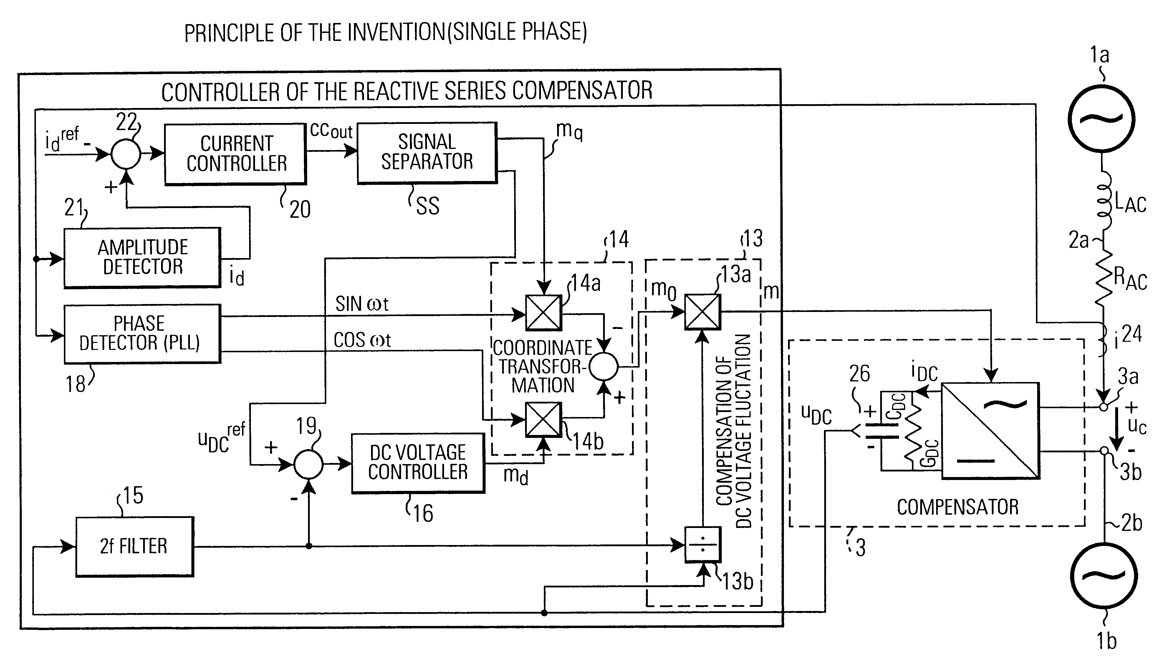
FIG. 20 shows a signal separator SS1. As explained above, the control signal cc.sub.out of the current controller 20 which is input to the signal separator SS1 is the amplitude of the compensator terminal output voltage u.sub.c. Since the maximum output voltage u.sub.c of the compensator is basically the maximum DC capacitor voltage, also the output of the current controller cc.sub.out has a maximum value determined by the maximum DC capacitor voltage.

In FIG. 20 a first limiter 200 is provided for limiting the control voltage cc.sub.out to a voltage level u.sub.DC.sup.min when the control voltage cc.sub.out exceeds this predetermined limit voltage u.sub.DC.sup.min. Likewise, if the control voltage cc.sub.out falls below the negative limit voltage -u.sub.DC.sup.min then the control voltage cc.sub.out will be limited to this negative limit voltage u.sub.DC.sup.min. Furthermore, a first divider 201 is provided for multiplying the output of the first limiter 200 with the maximum modulat...

second embodiment

A second embodiment of a signal separator SS2 having the control characteristics as shown in FIG. 22a is shown in FIG. 21. This signal separator SS2 comprises a third limiter 211 for limiting the control voltage cc.sub.out output by the current controller to a maximum modulation index m.sub.q.sup.max and a minimum modulation index m.sub.q.sup.min when the control voltage cc.sub.out respectively exceeds or falls below the maximum and minimum modulation indices, respectively. Thus, cc.sub.out is the modulation index level. The maximum modulation index m.sub.q.sup.min may be the negative value of m.sub.q.sup.max.

Furthermore, the signal separator SS2 comprises a second absolute value circuit 213 for determining the absolute value of the control voltage cc.sub.out. A first multiplier 212 multiplies the output of the absolute value circuit with a predetermined constant K.sub.2. A fourth limiter 214 limits the output of the second multiplier 212 to an upper threshold value u.sub.DC.sup.max...

third embodiment

A third embodiment of the signal separator SS3 incorporating such a rate limiter is shown is FIG. 23. The rate limiter 235 is provided in the lower path (responsible for the DC capacitor voltage adjustable control region). It may be arranged before the limiter 234 or after the limiter 234. In FIG. 23 the units 231, 232, 233 and 234 correspond to the units 200, 201, 202, 203 of the first embodiment in FIG. 20. The arrangement of the rate limiter 235 after the limiter 234 is preferable, because it avoids a rise-up delay from constant DC voltage to adjustable DC voltage.


PUM


Abstract

A controller for controlling a reactive series compensator serially inserted at compensator terminals into a power transmission line for controlling the line current. The controller includes a current control loop and a voltage control loop. A current controller outputs a control voltage (cc.sub.out) indicating a desired compensator terminal output voltage (u.sub.c). A control method selector means generates, in a low output voltage region, a constant reference voltage (u.sub.DC.sup.ref) for the voltage control loop and a variable modulation index mq of a modulation signal m=m.sub.d cos (.omega.t) -m.sub.q sin (.omega.t). In a high output voltage range, the control method selector outputs a constant modulation index m.sub.q and a variable reference voltage (u.sub.DC.sup.ref). The voltage controller outputs the modulation index m.sub.d of the modulation signal m. Furthermore, the control method selector can include a rate limiter for limiting the change rate of the reference voltage (u.sub.DC.sup.ref). In connection with the control method selection and / or the rate limiter, a decoupling control for making the voltage and current control loops independent from each other can be used. The controllers find particular application in transformerless reactive series compensators for single-phase or three-phase control.

Description

BACKGROUND OF THE INVENTIONFIELD OF THE INVENTIONThe invention relates to a controller for controlling a reactive series compensator serially inserted at compensator terminals into a power transmission line. Typically, in such a transformerless reactive series compensator an inverter control is performed in order to control the line current and / or the voltage applied from the compensator to the transmission line. The voltage / current control enables control of the flow of power from one end to the other end of the transmission line and a power flow into the inverter of the compensator in order to charge a capacitor which provides a compensator terminal output voltage at the compensator terminals.Typically, as will be explained below with more details, a current feedback control loop and a voltage feedback control loop are employed in order to respectively control the reactive and the active part of the line current. For doing so, the modulation signal based on which the PWM control o...

Claims


Application Information

Patent Timeline
Patent Type & Authority Patents(United States)
IPC IPC(8): G05F1/70H02J3/18
CPCG05F1/70H02J3/1807Y02E40/30
Inventor FUJII, TOSHIYUKIBEER, ANDREAS
Owner MITSUBISHI ELECTRIC CORP
Why Eureka
Try Eureka