Systems and methods for synthesis of extended length nanostructures

a nanostructure and nano-structure technology, applied in nanoinformatics, nanotechnology, nanotechnology, etc., can solve the problems of short nanotubes produced by these studies, limited composite material reinforcement, and limited diffusion of feedstock gas to the catalytic particle,

Active Publication Date: 2005-08-04
NANCOMP TECHNOLOGIES INC
View PDF15 Cites 231 Cited by
  • Summary
  • Abstract
  • Description
  • Claims
  • Application Information

AI Technical Summary

Benefits of technology

[0009] The present invention further provides, in one embodiment, a method for synthesizing nanostructures. The method includes, providing a porous substrate having an upstream surface and a downstream surface. Next, a plurality of catalyst particles may be deposited on to the downstream surface of the substrate. In one embodiment, the particles may be deposited directly onto the substrate by one of, precipitation of the particles solution, ball milling, sputtering, electrochemical reduction, or atomization. In another embodiment, the catalyst particles may be provided by chemical reduction of metallic salts deposited from solution and dried on to the substrate. In a further embodiment, catalyst particles may be provided by reduction of particles deposited from suspension and dried on to the substrate. In yet another

Problems solved by technology

However, the nanotubes that these studies produced have been short and are limited for composite material reinforcement, where longer tubes may be necessary to get good load transfer from tube to tube.
Thus, diffusion of feedstock gas to the catalytic particle can become limited as a forest of nanotube fibers grows from a collection of catalytic particles on the substrate.
The growing forest o

Method used


Image

  • Systems and methods for synthesis of extended length nanostructures
  • Systems and methods for synthesis of extended length nanostructures
  • Systems and methods for synthesis of extended length nanostructures

Examples


example i

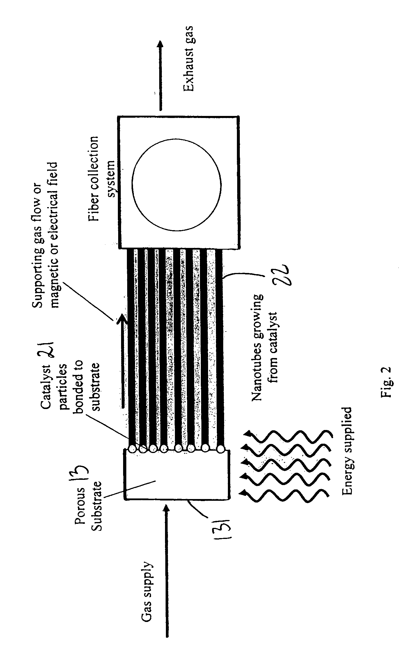
[0055] Prior to initiating the synthesis process, a porous substrate needs to be provided on which there can be deposited a concentration of catalyst particles for growing extended length nanotubes of extended length.

Substrate and Formation of Catalyst Particles

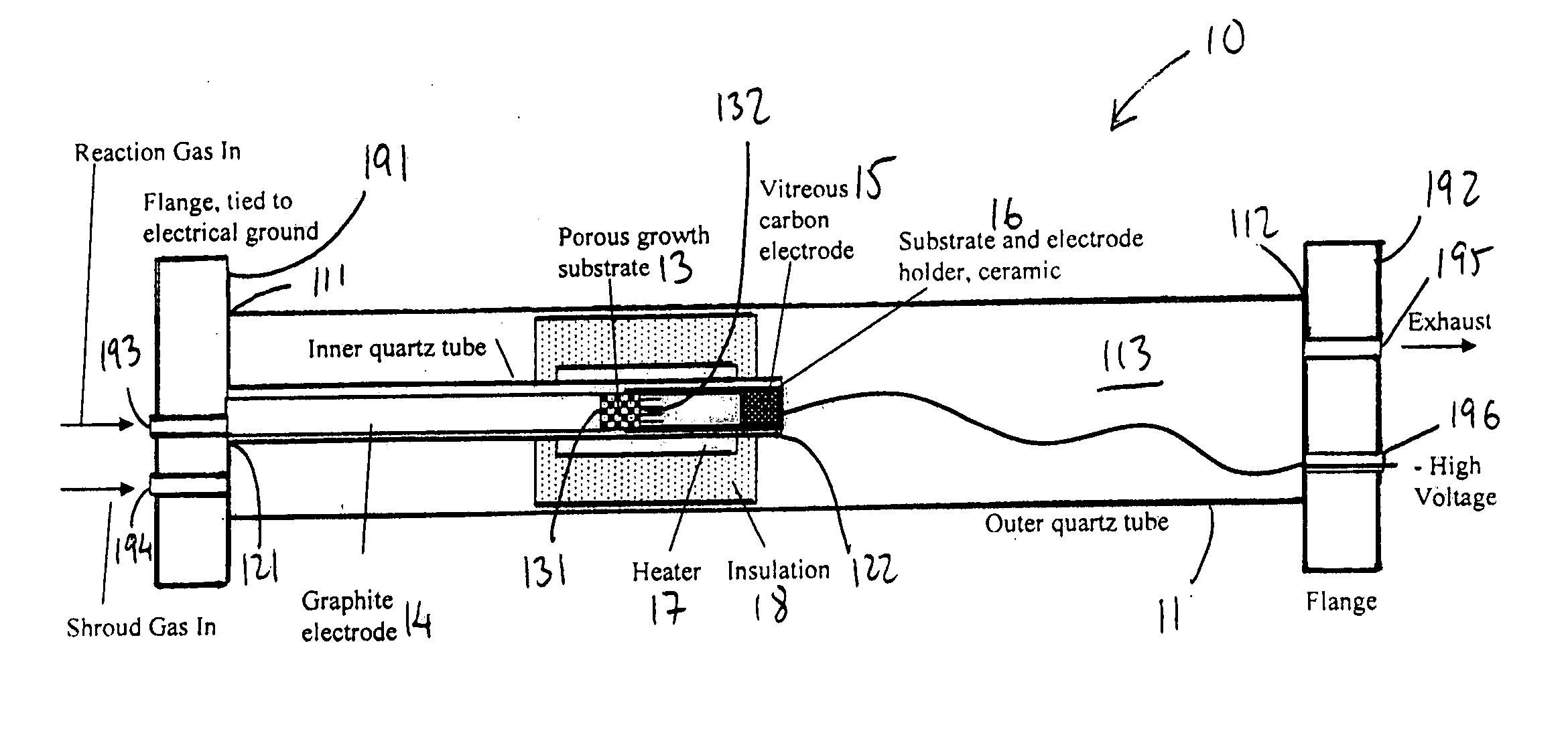
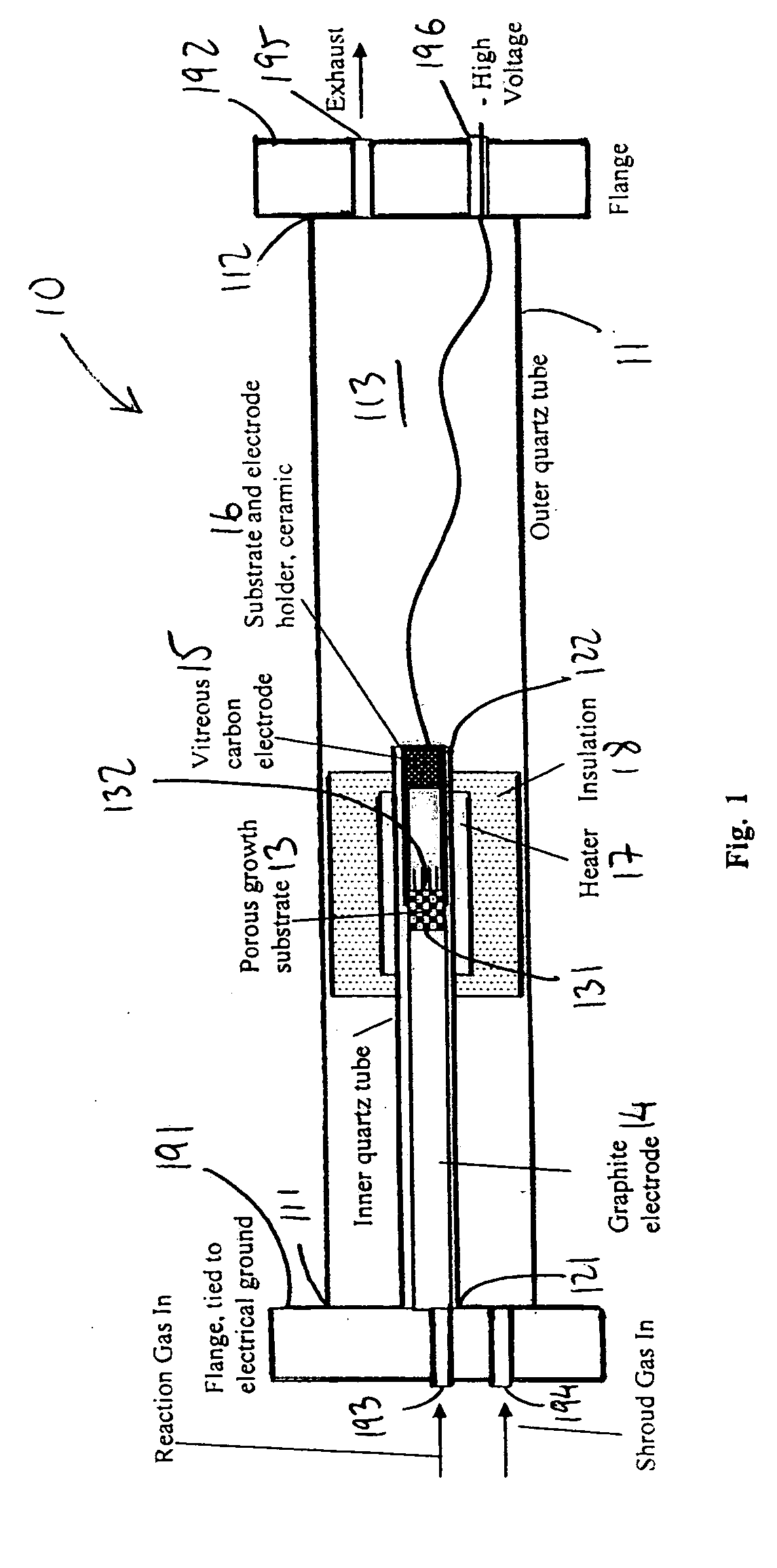
[0056] The substrate, in one embodiment, may be a porous alumina foam having approximately 50 micron to 200 micron pores and an approximately 50% to 90% void fraction. It should be noted that the substrate may be formed from various different materials, so long as the substrate can be provided with pores size ranging between 5 nm and 500 microns, and void fractions ranging between 10% and 95%. The alumina foam may initially be cut to fit into a holder, such as holder 16 in FIG. 1. Next, catalyst particles may be deposited onto the downstream surface of the substrate.

[0057] In one embodiment, approximately 0.05 grams of commercially available Ni nanoparticles, about 5 nm in diameter, may initially be dispersed in about 10 ...

example ii

[0093] The present invention provides, in another embodiment, a process for generating extended length prismatic structures. Prismatic structures, in on embodiment, can be an array of graphene planes joined to form a three dimensional lattice. The prismatic structures generated can have similar energy and carbon feedstock requirements as the reaction described above for the growth of carbon nanotubes. As such, the gas, energy and reaction conditions described above in connection with the growth of nanotubes also apply to the growth of prismatic carbon structures.

Catalyst Tiling for Prismatic Structures

[0094] Prismatic structures arise from the self-assembly of carbon on a different pattern of catalytic material than that used for formation of nanotubes. In accordance with one embodiment of the present invention, the nanotubes can be formed as carbon self-assembles around a catalyst ‘particle’ on a porous substrate. Prismatic structures, on the other hand, can be synthesized from ...


PUM

PropertyMeasurementUnit
Temperatureaaaaaaaaaa
Lengthaaaaaaaaaa

Abstract

A system for synthesizing nanostructures using chemical vapor deposition (CVD) is provided. The system includes a housing, a porous substrate within the housing, and on a downstream surface of the substrate, a plurality of catalyst particles from which nanostructures can be synthesized upon interaction with a reaction gas moving through the porous substrate. Electrodes may be provided to generate an electric field to support the nanostructures during growth. A method for synthesizing extended length nanostructures is also provided. The nanostructures are useful as heat conductors, heat sinks, windings for electric motors, solenoid, transformers, for making fabric, protective armor, as well as other applications.

Description

RELATED U.S. APPLICATION(S) [0001] This application claims priority to Provisional Application Ser. No. 60 / 536,767, filed Jan. 15, 2004, which application is hereby incorporated herein by reference.FIELD OF THE INVENTION [0002] The present invention relates to the synthesis of nanostructures, and more particularly, to the use of chemical vapor deposition (CVD) for the synthesis of such nanostructures. RELATED ART [0003] Carbon nanotubes have been known for some time. Examples of literature disclosing carbon nanotubes include, J. Catalysis, 37, 101 (1975); Journal of Crystal Growth 32, 35 (1976); “Formation of Filamentous Carbon”, Chemistry of Physics of Carbon, ed. Philip L. Walker, Jr. and Peter Thrower, Vol. 14, Marcel Dekker, Inc, New York and Basel, 1978; and U.S. Pat. No. 4,663,230, issued Dec. 6, 1984. More recent interest in carbon filamentary material was stimulated by a paper by Sumio Iijima in Nature 354, 56 (1991) describing a similar material. These early studies and the...

Claims


Application Information

Patent Timeline
IPC IPC(8): C01B31/02C23C16/00G21H5/00
CPCB82Y10/00Y10S977/702B82Y40/00C01B31/0233C01B2202/34Y10T428/2916Y10T428/298Y10T428/2918Y10S977/89Y10S977/70Y10S438/909Y10S977/844Y10S977/701Y10S977/963B82Y30/00C01B32/162Y10T442/60Y10T428/249978Y10T442/605
Inventor LASHMORE, DAVIDBROWN, JOSEPH J.DEAN, ROBERT C. JR.ANTOINETTE, PETER L.
Owner NANCOMP TECHNOLOGIES INC
Why Eureka
Try Eureka