Noise reduction system and method for audio switching amplifier

a technology of noise reduction and audio switching, applied in the direction of electronic switching, gain control, pulse technique, etc., can solve the problems of increasing the cost of voltage drop and power consumption of output-producing circuit elements, reducing the efficiency of audio switching amplifiers, and reducing the noise of audible noise (clicks and pops). the effect of noise reduction

Inactive Publication Date: 2008-05-15
ANALOG DEVICES INC
View PDF11 Cites 13 Cited by
  • Summary
  • Abstract
  • Description
  • Claims
  • Application Information

AI Technical Summary

Benefits of technology

[0007]It is therefore an object of this invention to provide an improved noise reduction system and method which reduces audible noise (clicks and pops) upon turn-on (un-muting) and turn-off (muting).
[0008]It is a further object of this invention to provide such an improved noise reduction system and method which is less sensitive to mismatch in filter components and small timing errors in start-up pulses.
[0009]It is a further object of this invention to provide such an improved noise reduction system and method which eliminates the cost, size and complexity associated with external relays.

Problems solved by technology

The pulse waveform minimizes v*i power dissipation across the switches, resulting in significantly less power consumption than ‘linear’ output stages, which can produce any voltage between the power supply levels, but at the cost of larger voltage drops and power consumption in the output-producing circuit elements.
However, the pulses also contain undesirable high-frequency energy, which can interfere with other electronics, or lead to undesirable noises or heating if input directly to the speaker.
A troublesome design problem in differential switching PWM amplifiers with demodulation filters is how to avoid undesirable clicks and pops (audible noise) when turning them on or off, muting or un-muting and the like.
The challenge is to somehow accomplish a transition between these dissimilar operating states without producing objectionable audible noise, clicks or pops, at the speaker.
This prevents problematic transients from reaching the speaker, but has disadvantages of extra cost and space.
This approach requires a special power supply which is capable of being ramped up and down, significantly increasing complexity and cost.

Method used


Image

  • Noise reduction system and method for audio switching amplifier
  • Noise reduction system and method for audio switching amplifier
  • Noise reduction system and method for audio switching amplifier

Examples


Embodiment Construction

[0035]Aside from the preferred embodiment or embodiments disclosed below, this invention is capable of other embodiments and of being practiced or being carried out in various ways. Thus, it is to be understood that the invention is not limited in its application to the details of construction and the arrangements of components set forth in the following description or illustrated in the drawings. If only one embodiment is described herein, the claims hereof are not to be limited to that embodiment. Moreover, the claims hereof are not to be read restrictively unless there is clear and convincing evidence manifesting a certain exclusion, restriction, or disclaimer.

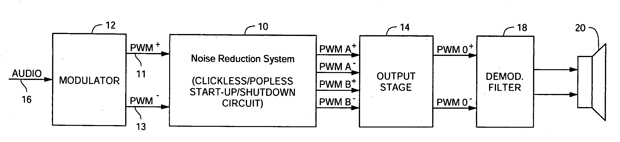
[0036]There is shown in FIG. 1 a differential audio switching amplifier with a noise reduction system 10 according to this invention also known as a clickless / popless start-up / shutdown circuit.

[0037]An audio input 16 is delivered to modulator 12 which provides at least one pulse width modulation signal PWM+ 11 from which ca...


PUM


Abstract

Noise reduction for a switching amplifier system having a differential output stage and demodulator filter responsive to complementary PWM signals includes generating in-phase PWM signals and gradually adjusting their duty cycle between a low duty cycle and the full duty cycle of the complementary PWM signals, generating full duty cycle PWM signals and gradually shifting their relative phase between in-phase and out-of-phase; and in response to a turn-on signal, adjusting the in-phase PWM signals from low to full duty cycle and shifting the relative phase from in-phase to out-of-phase, and in response to a turn-off signal shifting the relative phase from out-of-phase to in-phase and adjusting the in-phase PWM signals from full to low duty cycle for maintaining balanced charge on the demodulation filter to reduce audible noise.

Description

FIELD OF THE INVENTION[0001]This invention relates to a noise reduction system and method which reduces audible noise upon turn-on (un-muting) and turn-off (muting) in an audio switching amplifier.BACKGROUND OF THE INVENTION[0002]Switching audio amplifiers achieve high power efficiency by using a special (switching) output stage, which outputs pulses that switch between the positive power supply voltage and negative power supply voltage of the output stage. To produce the pulses, the output stage contains switches to connect its output to the desired power supply. The pulse waveform minimizes v*i power dissipation across the switches, resulting in significantly less power consumption than ‘linear’ output stages, which can produce any voltage between the power supply levels, but at the cost of larger voltage drops and power consumption in the output-producing circuit elements.[0003]In a switching audio amplifier, a modulator converts an input audio signal into a pulse sequence for us...

Claims


Application Information

Patent Timeline
Patent Type & Authority Applications(United States)
IPC IPC(8): H03F3/38
CPCH03F1/26H03F1/305H03F3/2173H03F3/393H03F2200/03H03K17/6871H03F2200/372H03F2200/78H03G3/348H03K7/08H03K17/002H03F2200/351
Inventor MENARD, GABRIELGAALAAS, ERIC
Owner ANALOG DEVICES INC
Why Eureka
Try Eureka