
Reduced Input Power Cryogenic Refrigerator

a cryogenic refrigerator and input power technology, applied in gas cycle refrigeration machines, refrigeration machines, solidification, etc., can solve the problems of large pressure difference through the valve, low efficiency of valved cryogenic refrigerators, and low efficiency of early pulse tube refrigerators, so as to reduce the amount of gas that needs to be supplied by the compressor and reduce the loss of pressure through the valve

Inactive Publication Date: 2008-04-24
SUMITOMO HEAVY IND LTD +1
View PDF23 Cites 16 Cited by
  • Summary
  • Abstract
  • Description
  • Claims
  • Application Information

AI Technical Summary

Benefits of technology

[0008] It has been found that a valved cryogenic refrigerator can be designed, such that part of the gas flow between the compressor and the expander can be supplied from and discharged to a valved connection to a buffer volume. The pressure drop loss through the valve is reduced with the invented concept and the amount of gas that needs to be supplied by the compressor is reduced.
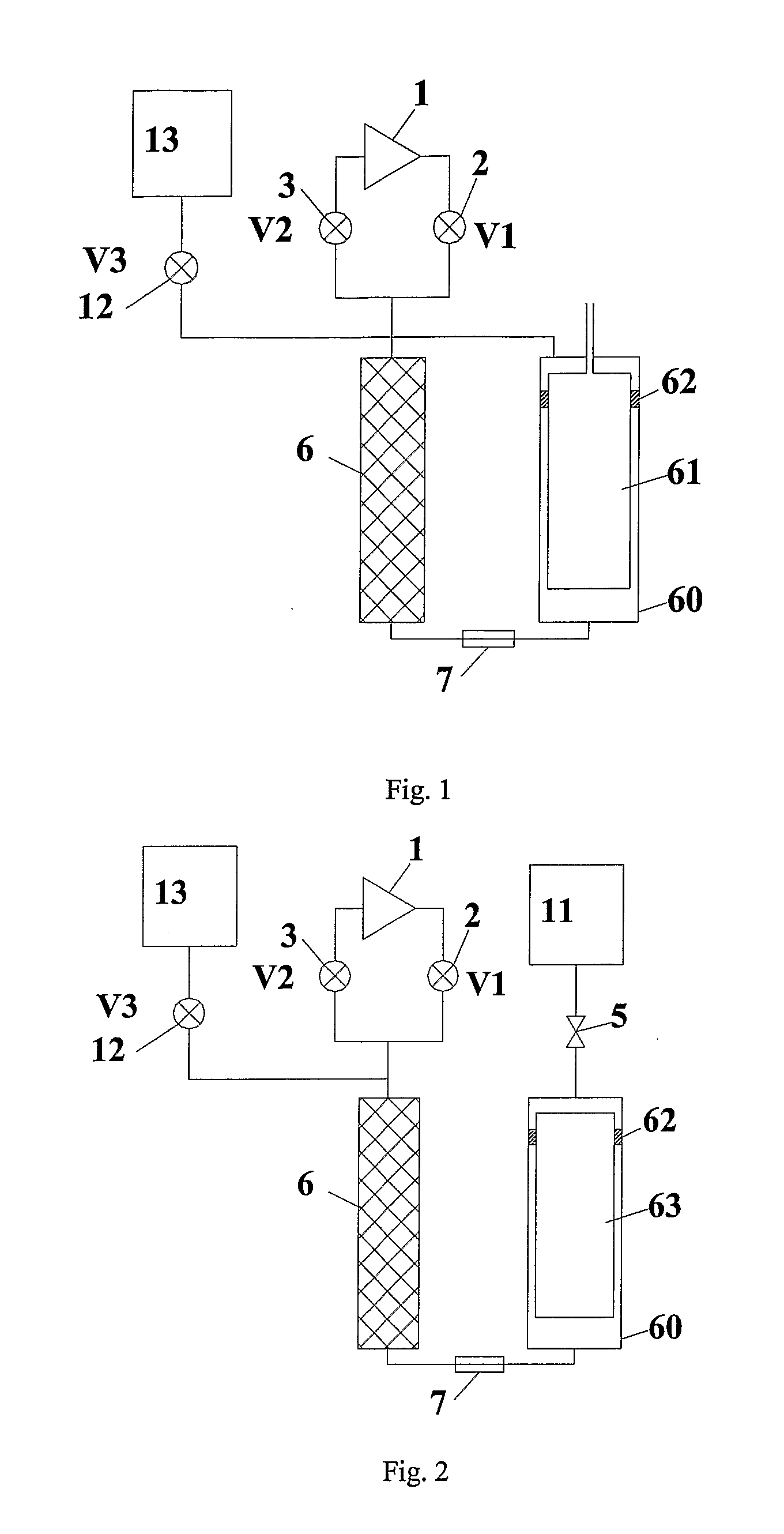
[0009] This invention provides a means of reducing the power input to a GM or GM type pulse tube refrigerator. A buffer volume stores gas that flows to and from the warm end of the regenerator through a valve that opens and closes during the periods when the main supply and return valves are closed and is closed when the main supply and return valves are open. During the charging process, gas is charged into the regenerator from one or more buffer volumes instead of the supply side of the compressor when pressure at the inlet of the regenerator is lower than the pressure in the buffer. During the discharging process, gas is discharged from the regenerator to the buffer instead of the return side of the compressor when pressure at the inlet of the regenerator is higher than the pressure in the buffer. The net effect is to reduce the amount of gas that is supplied by the compressor thus increasing the system efficiency. In addition, the pressure difference through the valves may be reduced, the gas flow velocity may be lower, and the audible noise may be reduced as the gas flow velocity is reduced.

Problems solved by technology

Early pulse tube refrigerators were not efficient enough to compete with GM type refrigerators.
This type of valved cryogenic refrigerator has the disadvantage of low efficiency due to the pressurization and depressurization of the void volumes in the expander as gas cycles in and out of the expander.
On the other hand, when the low pressure valve opens, there is also a large pressure difference through the valve, because the pressure at the inlet of the regenerator is near the high pressure.
This process generates an irreversible loss which cannot be decreased by enlarging the opening area of the valves.

Method used


Image

  • Reduced Input Power Cryogenic Refrigerator
  • Reduced Input Power Cryogenic Refrigerator
  • Reduced Input Power Cryogenic Refrigerator

Examples


Embodiment Construction

[0039] The present invention is applicable to any kind of refrigerator in which gas is cycled in and out of the expander by a valve unit, including G-M refrigerators, Solvay refrigerators, and G-M type pulse tube refrigerators. It is of particular value when applied to low temperature pulse tubes that have multi-stages.

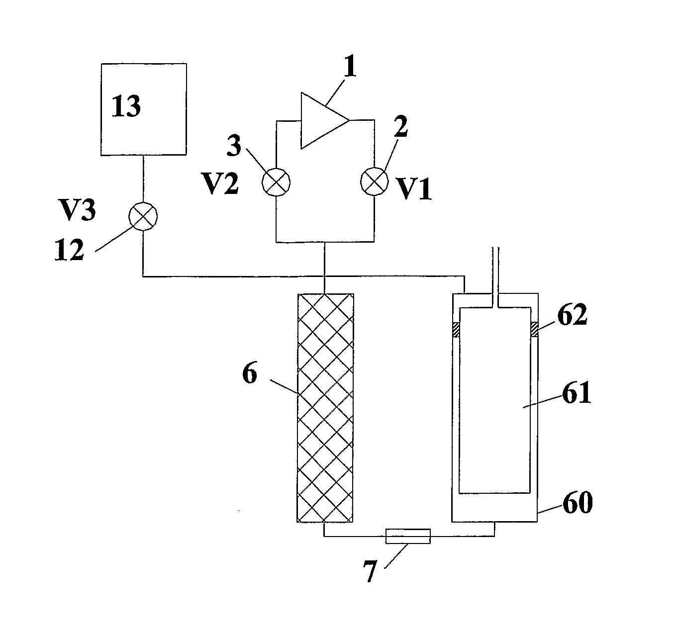
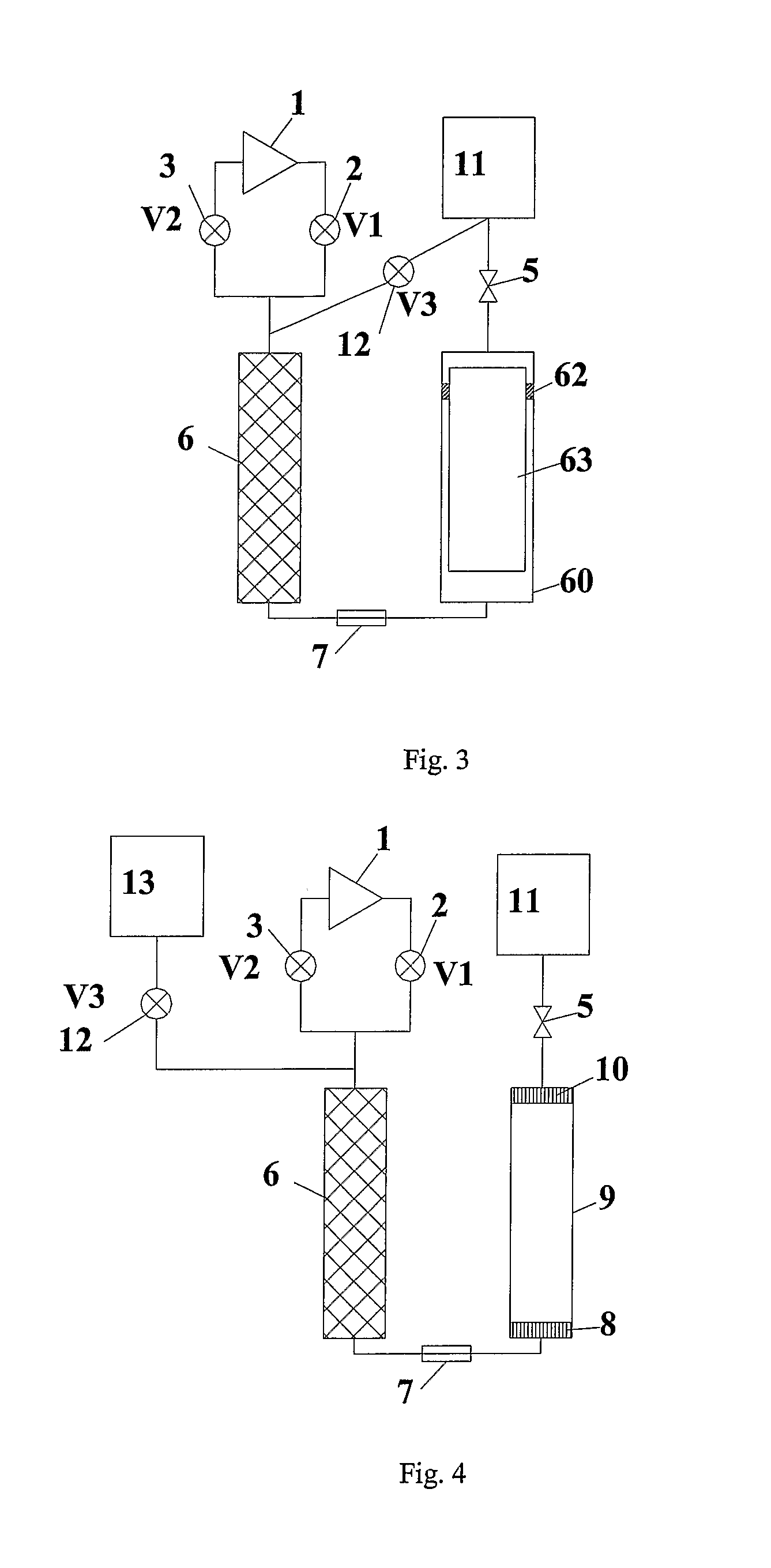
[0040]FIG. 1 is a schematic of a G-M refrigerator with a mechanical displacer drive along with small schematics of a compressor 1 a buffer volume 13 and three on-off valves. The three on-off valves cycle gas in and out of regenerator 6. Valve 2, V1, controls gas flowing between the supply side of compressor 1 and the inlet of regenerator 6. Valve 3, V2, controls gas flowing between the inlet of regenerator 6 and the return side of the compressor. Valve 12, V3, controls gas flowing between the inlet of regenerator 6 and power reduction buffer volume 13. V1, V2 and V3 open and close according to the timing sequence as shown in FIG. 17. A displacer 61 is enclosed in a c...


PUM


Abstract

The present invention relates to valved cryogenic refrigerators, in particular, Gifford McMahon (GM) refrigerators, and GM type pulse tube refrigerators where gas is cycled between high and low pressures by a valve mechanism that connects to an expander. Input power is reduced by use of a buffer volume which stores gas that flows to and from the warm end of the regenerator through a valve that opens and closes during the periods when the main supply and return valves are closed and is closed when the main supply and return valves are open.

Description

BACKGROUND OF THE INVENTION [0001] The present invention relates to valved cryogenic refrigerators, in particular, Gifford McMahon (GM) refrigerators, and GM type pulse tube refrigerators. Gas is cycled between high and low pressures by a valve mechanism that connects to an expander. The valve mechanism commonly consists of a rotary valve disc and a valve seat. Rotary disc valves lend themselves to being designed with multiple ports. There are discrete ports, which, by periodic alignment of the different ports, allow the passage of a working fluid, supplied by a compressor, to and from the regenerators and working volumes of the expander. [0002] GM and Solvay type refrigerators use compressors that supply gas at a nearly constant high pressure and receive gas at a nearly constant low pressure. The gas is supplied to a reciprocating expander that runs at a low speed relative to the compressor by virtue of the valve mechanism that alternately lets gas in and out of the expander. [0003...

Claims


Application Information

Patent Timeline
IPC IPC(8): F25J1/00
CPCF25B9/14F25B9/145F25B2309/1408F25B2600/2519F25B2309/1418F25B2309/1424F25B2309/14241F25B2309/1411
Inventor XU, MINGYAOGAO, JIN LIN
Owner SUMITOMO HEAVY IND LTD
Learn More