Dielectric antenna

a technology of dielectric antennas and antennas, applied in the direction of leaky waveguide antennas, waveguide horns, electrical equipment, etc., can solve the problems of directivity reduction and phase front warping, and achieve the effect of high bundling

Active Publication Date: 2013-01-15
KROHNE MESSTECHNICK GMBH & CO KG
View PDF17 Cites 152 Cited by
  • Summary
  • Abstract
  • Description
  • Claims
  • Application Information

AI Technical Summary

Benefits of technology

[0008]It is, thus, the object of the present invention to provided a dielectric antenna, which is adaptable as low-loss as possible to different mounting situations, which additionally is as low-reflection as possible and, at the same time is highly bundling.
[0009]The above derived and described object is met according to the invention with a dielectric antenna of the type mentioned above in that the emitting section is designed as a dielectric tube connecting to the second transition section. In the dielectric antenna according to the invention, the second transition section consequently acts as a “real” transition section between bodily separated sections of the dielectric antenna, namely between the first transition section comprising a dielectric rod and the emitting section. The further guiding of the electromagnetic waves via the emission-side dielectric tube has the advantage that, at optimal—i.e. pure-mode—excitation, a substantial variability of the length of the dielectric antenna is achieved.

Problems solved by technology

When the modes excited by the discontinuities lie under the cut-off frequency of the natural wave system of the dielectric antenna, the higher modes cannot be guided along the dielectric structures, but the related electromagnetic radiation is directly emitted into space at the location of the discontinuities, which leads to a warping of the phase fronts and thus to a reduction of the directivity.

Method used


Image

  • Dielectric antenna
  • Dielectric antenna
  • Dielectric antenna

Examples


Embodiment Construction

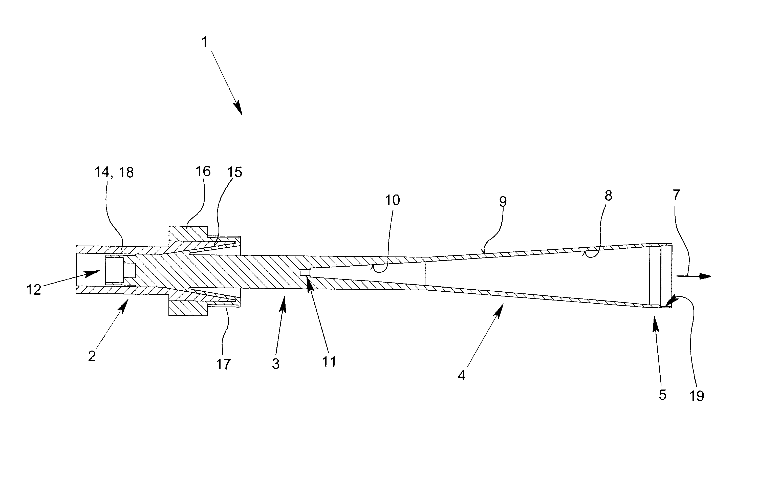
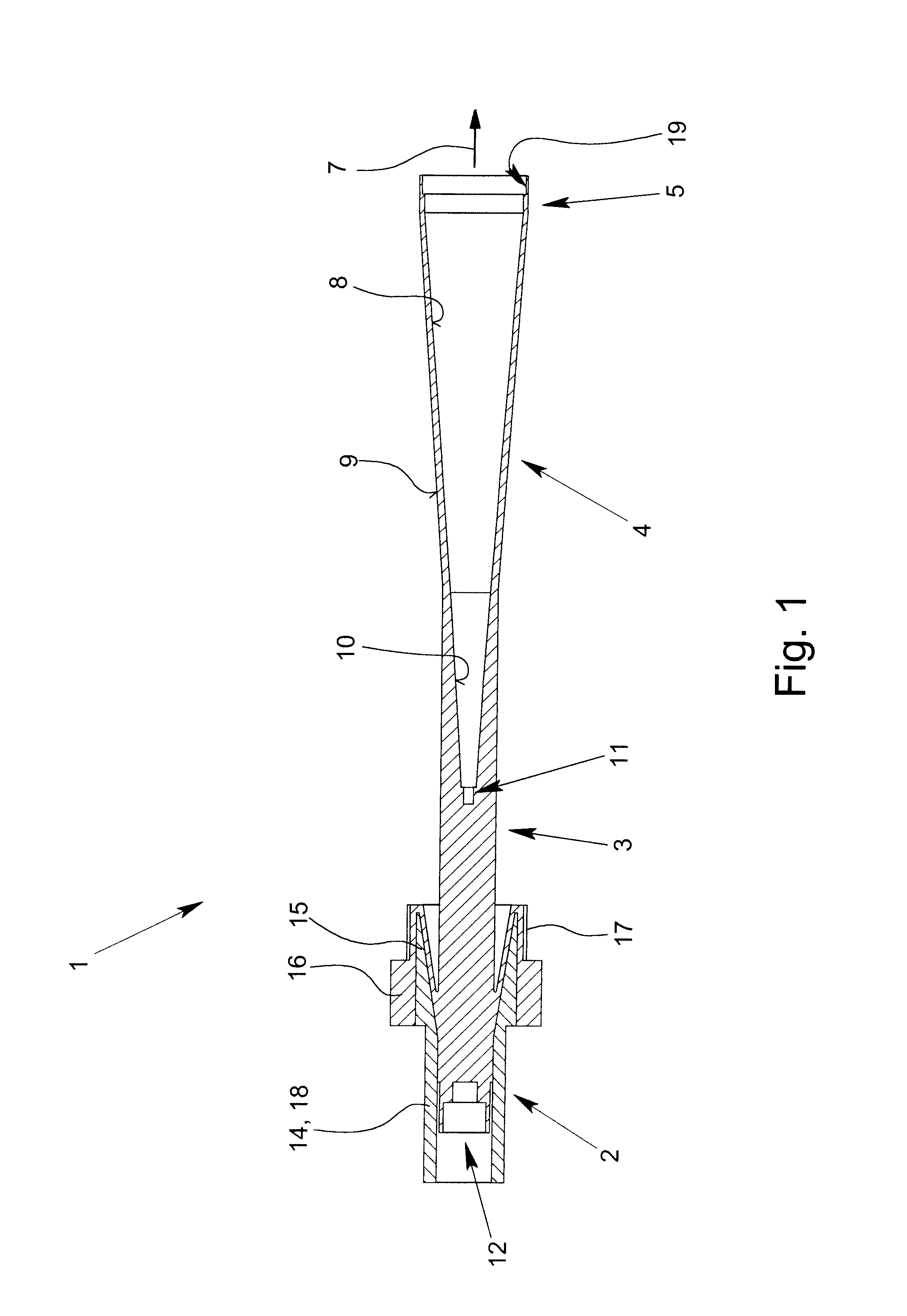
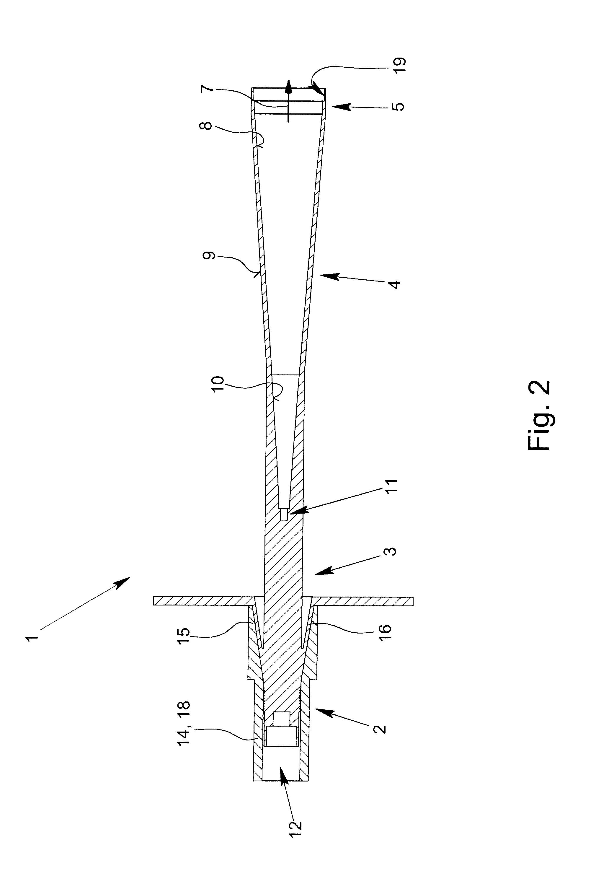
[0027]Cross-sections of complete dielectric antennae 1 are represented in FIGS. 1 and 2, which have a dielectric feeding section 2, a first transition section 3 comprising a dielectric rod, a dielectric emitting section 5 and, a further, second transition section 4 forming a dielectric horn, wherein the feeding section 2 can be struck with electromagnetic radiation 6, electromagnetic radiation 6 can be guided with the first transition section 3 and the second transition section 4 and electromagnetic radiation can be emitted from the emitting section 5 as airborne waves.

[0028]All of the dielectric antennae 1 shown in FIGS. 1 to 3—more or less true to detail—are characterized in that the emitting section 5 is designed as a dielectric tube connected to the second transition section 4. This measure achieves that the length of the dielectric antennae can be varied in large areas, namely using different choices of the length of the first transition section 3 including the dielectric rod a...


PUM


Abstract

Described and shown is a dielectric antenna (1) having a dielectric feeding section (2), a first transition section (3) comprising a dielectric rod, a dielectric emitting section (5) and, a further, second transition section (4) forming a dielectric horn, wherein the feeding section (2) can be struck with electromagnetic radiation (6), electromagnetic radiation (6) can be guided with the first transition section (3) and the second transition section (4) and the electromagnetic radiation can be emitted from the emitting section (5) as airborne waves.The object of the present invention is to provide a dielectric antenna, which is adaptable as low-loss as possible to different mounting situations, which additionally is as low-reflection as possible and, at the same time is highly bundling.The object of the above-mentioned dielectric antenna is met in that the emitting section (5) is designed as dielectric tube connecting to the second transition section (4).

Description

BACKGROUND OF THE INVENTION[0001]1. Field of the Invention[0002]The invention relates to a dielectric antenna having a dielectric feeding section, a first transition section comprising a dielectric rod, a dielectric emitting section, and, a further, second transition section forming a dielectric horn and, wherein the feeding section can be struck with electromagnetic radiation, electromagnetic radiation can be guided with the first transition section and the second transition section and the electromagnetic radiation can be emitted from the emitting section as airborne waves.[0003]2. Description of Related Art[0004]Dielectric antennae per se have been known for a long time and are used in different forms and sizes for very different purposes, as, for example, also in industrial process control for determining distances—for example of media surfaces in tanks—using running time evaluation of reflected electromagnetic waves (radar applications). The invention described here is complete...

Claims


Application Information

Patent Timeline
Patent Type & Authority Patents(United States)
IPC IPC(8): H01Q13/00
CPCH01Q1/225H01Q19/08H01Q13/24H01Q13/02
Inventor ARMBRECHT, GUNNARZIETZ, CHRISTIANDENICKE, ECKHARD
Owner KROHNE MESSTECHNICK GMBH & CO KG
Why Eureka
Try Eureka