Thermally-assisted magnetic recording head having a waveguide and a return path section

a magnetic recording head and waveguide technology, applied in the field of magnetic recording heads with magnetic assistance, can solve the problems of increasing the coercivity of the recording medium, the loss of magnetic fine particles in the thermal stability of magnetization, and the difficulty of data writing with existing magnetic heads, etc., to achieve excellent write characteristics and low coil resistance

Active Publication Date: 2013-07-30
HEADWAY TECH INC +1
View PDF6 Cites 8 Cited by
  • Summary
  • Abstract
  • Description
  • Claims
  • Application Information

AI Technical Summary

Benefits of technology

[0015]It is an object of the present invention to provide a thermally-assisted magnetic recording head configured so that the core of a waveguide and a return path section intersect each other without contacting each other, the thermally-assisted magnetic recording head exhibiting excellent write characteristics in a high frequency band and being low in coil resistance.

Problems solved by technology

Making the magnetic fine particles smaller, however, causes the problem that the magnetic fine particles drop in the thermal stability of magnetization.
However, increasing the anisotropic energy of the magnetic fine particles leads to an increase in coercivity of the recording medium, and this makes it difficult to perform data writing with existing magnetic heads.
This causes components around the coil to expand, thus causing part of the medium facing surface to protrude toward a recording medium and become more likely to collide with the recording medium.
However, this would lead to deterioration in write characteristics such as the overwrite property or to an increase in error rate.
This makes the coil higher in resistance, thus causing the above-described various problems to occur noticeably.

Method used


Image

  • Thermally-assisted magnetic recording head having a waveguide and a return path section
  • Thermally-assisted magnetic recording head having a waveguide and a return path section
  • Thermally-assisted magnetic recording head having a waveguide and a return path section

Examples


first embodiment

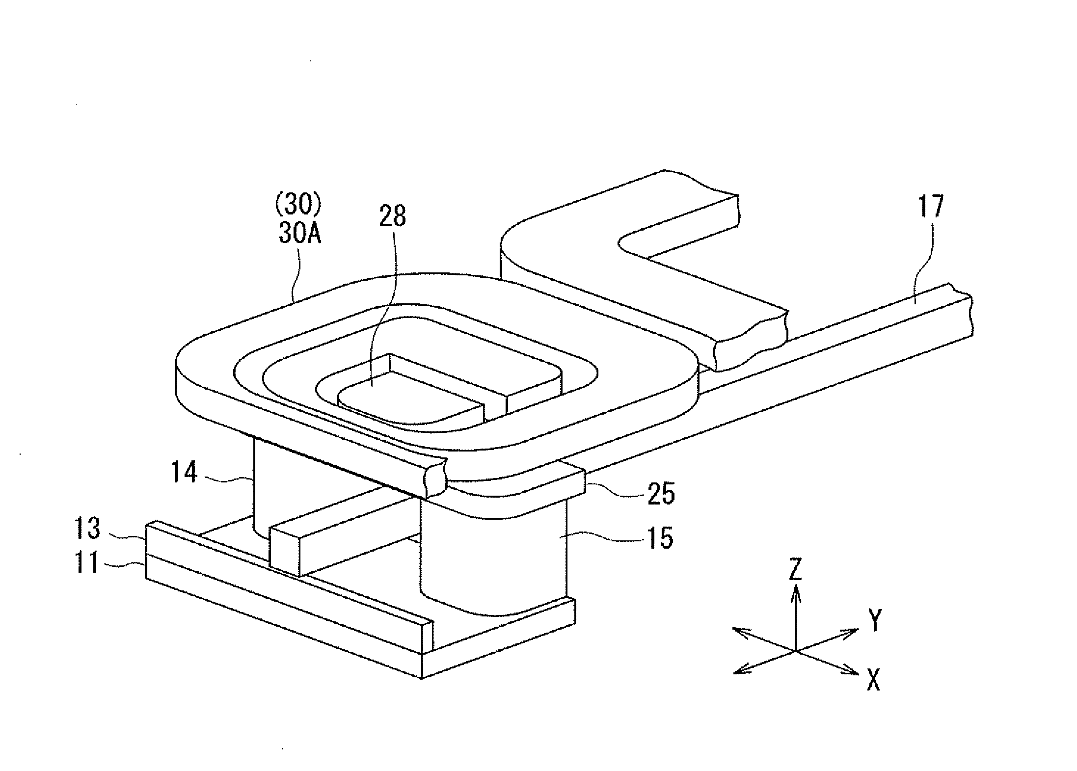
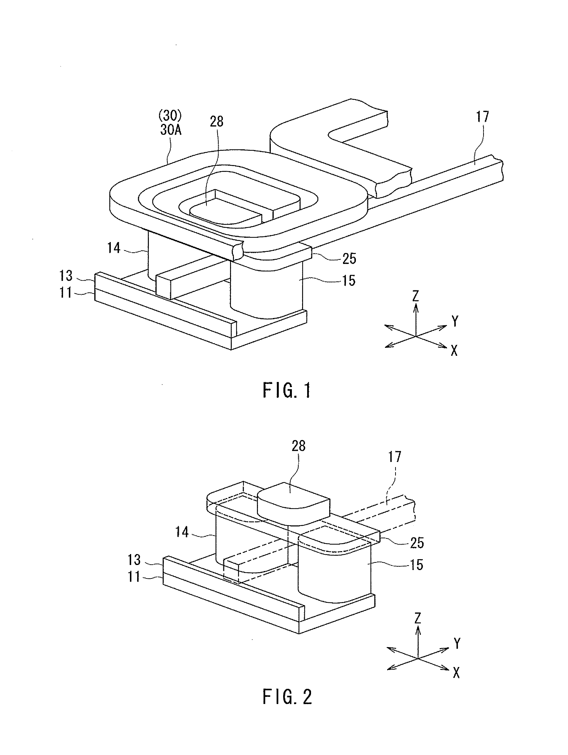
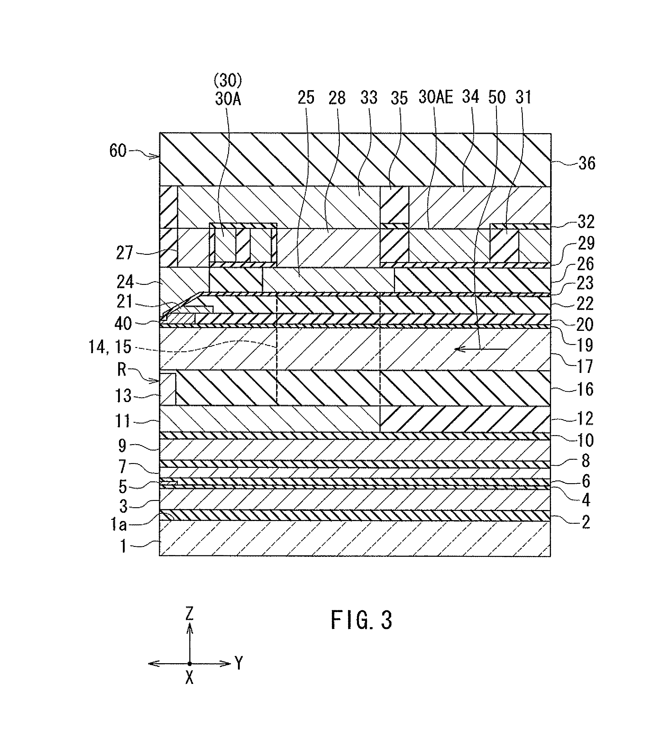
[0048]Preferred embodiments of the present invention will now be described in detail with reference to the drawings. First, reference is made to FIG. 1 to FIG. 6 to describe the configuration of a thermally-assisted magnetic recording head according to a first embodiment of the invention. FIG. 1 is a perspective view showing the main part of the thermally-assisted magnetic recording head. FIG. 2 is a perspective view showing a part of FIG. 1. FIG. 3 is a cross-sectional view showing the configuration of the thermally-assisted magnetic recording head. FIG. 4 is a front view showing the medium facing surface of the thermally-assisted magnetic recording head. FIG. 5 is a plan view showing a coil of the present embodiment. FIG. 6 is a cross-sectional view showing a core, a plasmon generator, and a main pole of the present embodiment.

[0049]The thermally-assisted magnetic recording head according to the present embodiment is for use in perpendicular magnetic recording, and is in the form ...

second embodiment

[0100]A thermally-assisted magnetic recording head according to a second embodiment of the invention will now be described with reference to FIG. 8 to FIG. 11. FIG. 8 is a perspective view showing the main part of the thermally-assisted magnetic recording head. FIG. 9 is a cross-sectional view showing the configuration of the thermally-assisted magnetic recording head. FIG. 10 is a plan view showing a second winding portion of the coil. FIG. 11 is a plan view showing a first winding portion of the coil.

[0101]The configuration of the thermally-assisted magnetic recording head according to the present embodiment is different from that of the head according to the first embodiment as follows. In the thermally-assisted magnetic recording head according to the present embodiment, as shown in FIG. 11, the first winding portion 30A of the coil 30 is wound approximately one turn around the third columnar portion 28. The first winding portion 30A has only a single linear conductor portion 30...

third embodiment

[0107]A thermally-assisted magnetic recording head according to a third embodiment of the invention will now be described with reference to FIG. 12 to FIG. 14. FIG. 12 is a cross-sectional view showing the configuration of the thermally-assisted magnetic recording head. FIG. 13 is a plan view showing a first layer of a first winding portion of the coil. FIG. 14 is a plan view showing a second layer of the first winding portion of the coil.

[0108]The configuration of the thermally-assisted magnetic recording head according to the present embodiment is different from that of the head according to the first embodiment as follows. In the thermally-assisted magnetic recording head according to the present embodiment, the coupling layer 27 of the return path section R includes a first layer 27A and a second layer 27B stacked in this order on the main pole 24, and the third columnar portion 28 includes a first layer 28A and a second layer 28B stacked in this order on the coupling portion 25...


PUM

PropertyMeasurementUnit
widthaaaaaaaaaa
heightaaaaaaaaaa
lengthaaaaaaaaaa

Abstract

A thermally-assisted magnetic recording head includes a coil, a main pole, a return path section, a waveguide, and a plasmon generator. The waveguide includes a core and a cladding. The return path section includes: first and second columnar portions located on opposite sides of the core in the track width direction; a coupling portion coupling the first and second columnar portions to each other; and a third columnar portion connected to the coupling portion. The third columnar portion is smaller than the coupling portion in width in the track width direction. The coil includes a winding portion wound around the third columnar portion.

Description

BACKGROUND OF THE INVENTION[0001]1. Field of the Invention[0002]The present invention relates to a thermally-assisted magnetic recording head for use in thermally-assisted magnetic recording where a recording medium is irradiated with near-field light to lower the coercivity of the recording medium for data writing.[0003]2. Description of the Related Art[0004]Recently, magnetic recording devices such as magnetic disk drives have been improved in recording density, and thin-film magnetic heads and recording media of improved performance have been demanded accordingly. Among the thin-film magnetic heads, a composite thin-film magnetic head has been used widely. The composite thin-film magnetic head has such a structure that a read head section including a magnetoresistive element (hereinafter, also referred to as MR element) for reading and a write head section including an induction-type electromagnetic transducer for writing are stacked on a substrate. In a magnetic disk drive, the ...

Claims


Application Information

Patent Timeline
Patent Type & Authority Patents(United States)
IPC IPC(8): G11B11/00
CPCG11B5/1278G11B5/3116G11B5/314G11B2005/0021
Inventor SASAKI, YOSHITAKAITO, HIROYUKISATO, KAZUKIARAKI, HIRONORITANEMURA, SHIGEKIFUJII, RYUJI
Owner HEADWAY TECH INC
Why Eureka
Try Eureka