Thermally-assisted magnetic recording head including a plasmon generator

a magnetic recording and magnetic recording technology, applied in the direction of maintaining the carrier alignment of the recording head, recording information storage, instruments, etc., can solve the problems of increasing the coercivity of the recording medium, the loss of magnetic fine particles in the thermal stability of magnetization, and the difficulty in performing data writing with existing magnetic recording heads, etc., to achieve excellent write characteristics

Active Publication Date: 2016-03-01
HEADWAY TECH INC +1
View PDF38 Cites 0 Cited by
  • Summary
  • Abstract
  • Description
  • Claims
  • Application Information

AI Technical Summary

Benefits of technology

[0018]It is an object of the present invention to provide a thermally-assisted magnetic recording head in which a near-field light generating part of a plasmon generator is located between an end face of a main pole and an end face of a shield in the medium facing surface, the thermally-assisted magnetic recording head exhibiting excellent write characteristics in a high frequency band and being capable of protecting the plasmon generator.
[0030]In the thermally-assisted magnetic recording head of the present invention, the first yoke portion, the second yoke portion and the first columnar portion are located on the front side in the direction of travel of the recording medium relative to the core, and the coil is wound around the first columnar portion. These features of the present invention make it possible to reduce the length of the magnetic path formed by the main pole, the shield and the return path section, while preventing an increase in resistance of the coil.
[0031]Further, in the thermally-assisted magnetic recording head of the present invention, the heater and the expansion layer are located on the rear side in the direction of travel of the recording medium relative to the core. This feature of the present invention makes it possible that a portion of the medium facing surface to be protruded by the expansion layer is located closer to the recording medium than is the near-field light generating part of the plasmon generator, thus allowing for protection of the plasmon generator.
[0032]Consequently, the present invention is able to provide a thermally-assisted magnetic recording head in which the near-field light generating part of the plasmon generator is located between the end face of the main pole and the end face of the shield in the medium facing surface, the thermally-assisted magnetic recording head exhibiting excellent write characteristics in a high frequency band and being capable of protecting the plasmon generator.

Problems solved by technology

Making the magnetic fine particles smaller, however, causes the problem that the magnetic fine particles drop in the thermal stability of magnetization.
However, increasing the anisotropic energy of the magnetic fine particles leads to an increase in coercivity of the recording medium, and this makes it difficult to perform data writing with existing magnetic heads.
This gives rise to a problem that components around the coil expand and as a result, part of the medium facing surface protrudes toward the recording medium and may readily collide with the recording medium.
However, this would disadvantageously lead to deterioration in write characteristics such as the overwrite property or to an increase in error rate.
This in turn causes the coil to be higher in resistance, so that the above-described various problems will become more noticeable.
Accordingly, in this case, it is difficult to reduce the length of the magnetic path formed by the main pole, the shield and the return path section.
Further, a thermally-assisted magnetic recording head has the following problems.
If the portion of the protective film near the plasmon generator is broken, the plasmon generator may be damaged by contact with the recording medium or may be corroded by contact with high temperature air.

Method used


Image

  • Thermally-assisted magnetic recording head including a plasmon generator
  • Thermally-assisted magnetic recording head including a plasmon generator
  • Thermally-assisted magnetic recording head including a plasmon generator

Examples


first embodiment

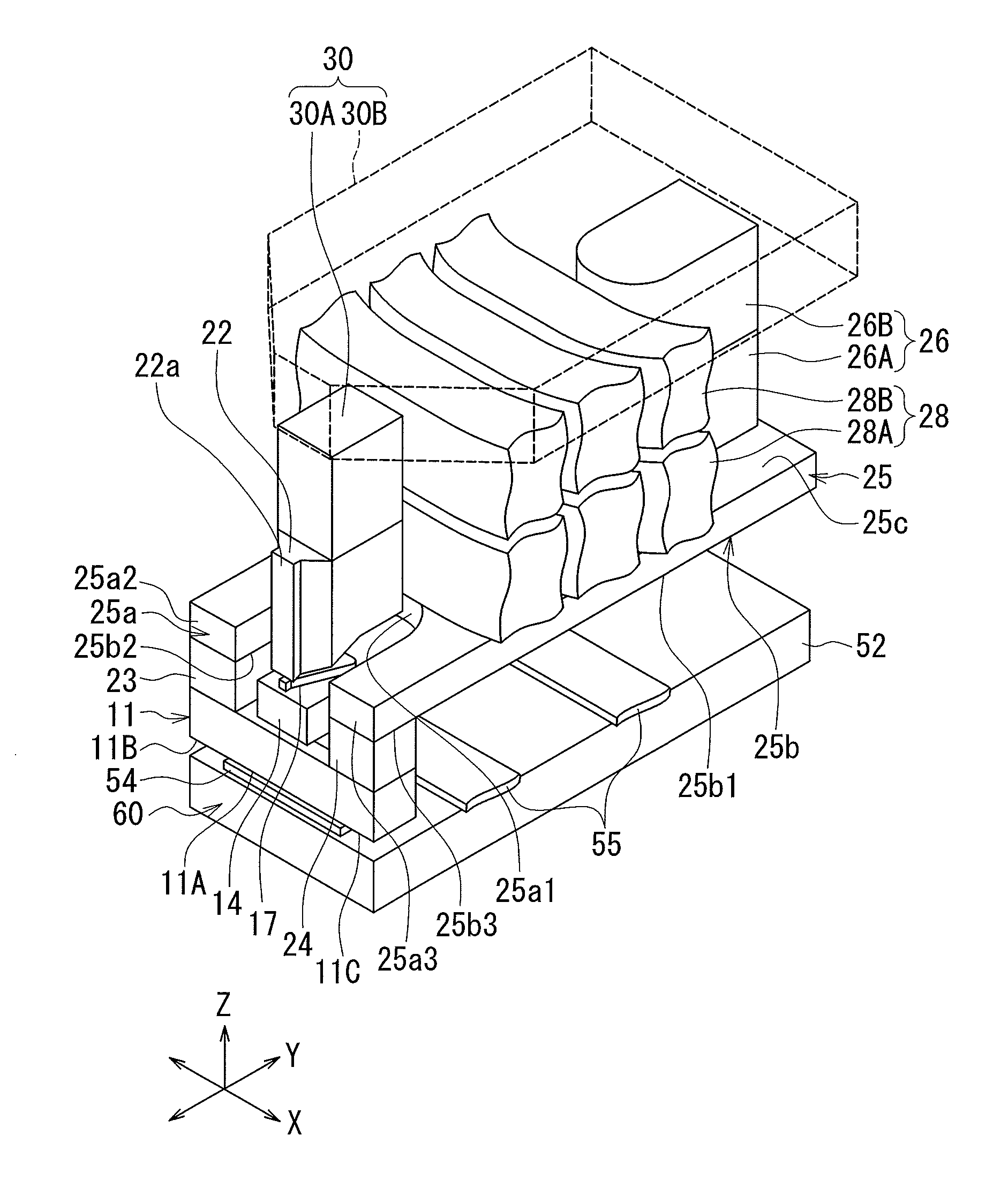
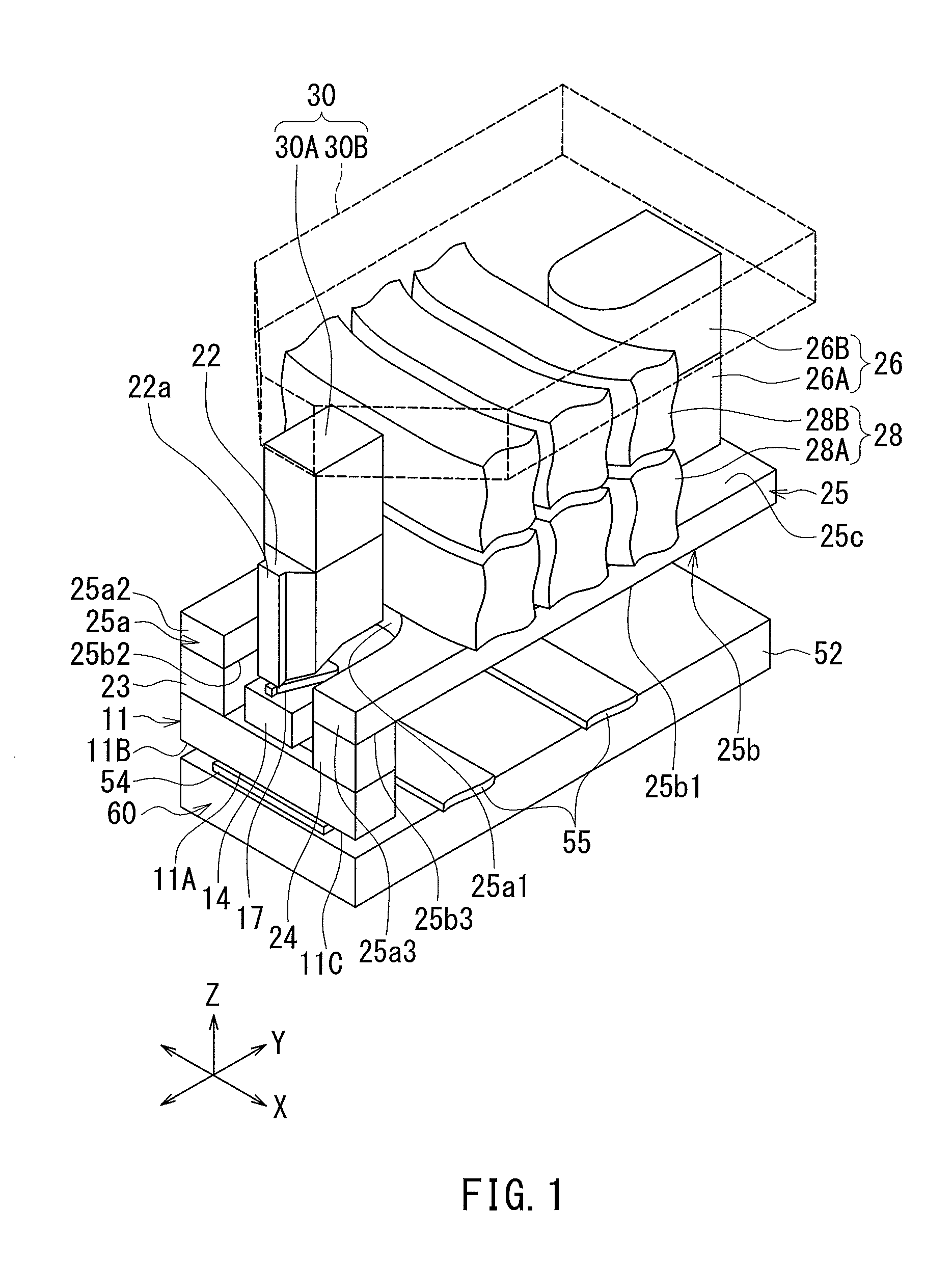
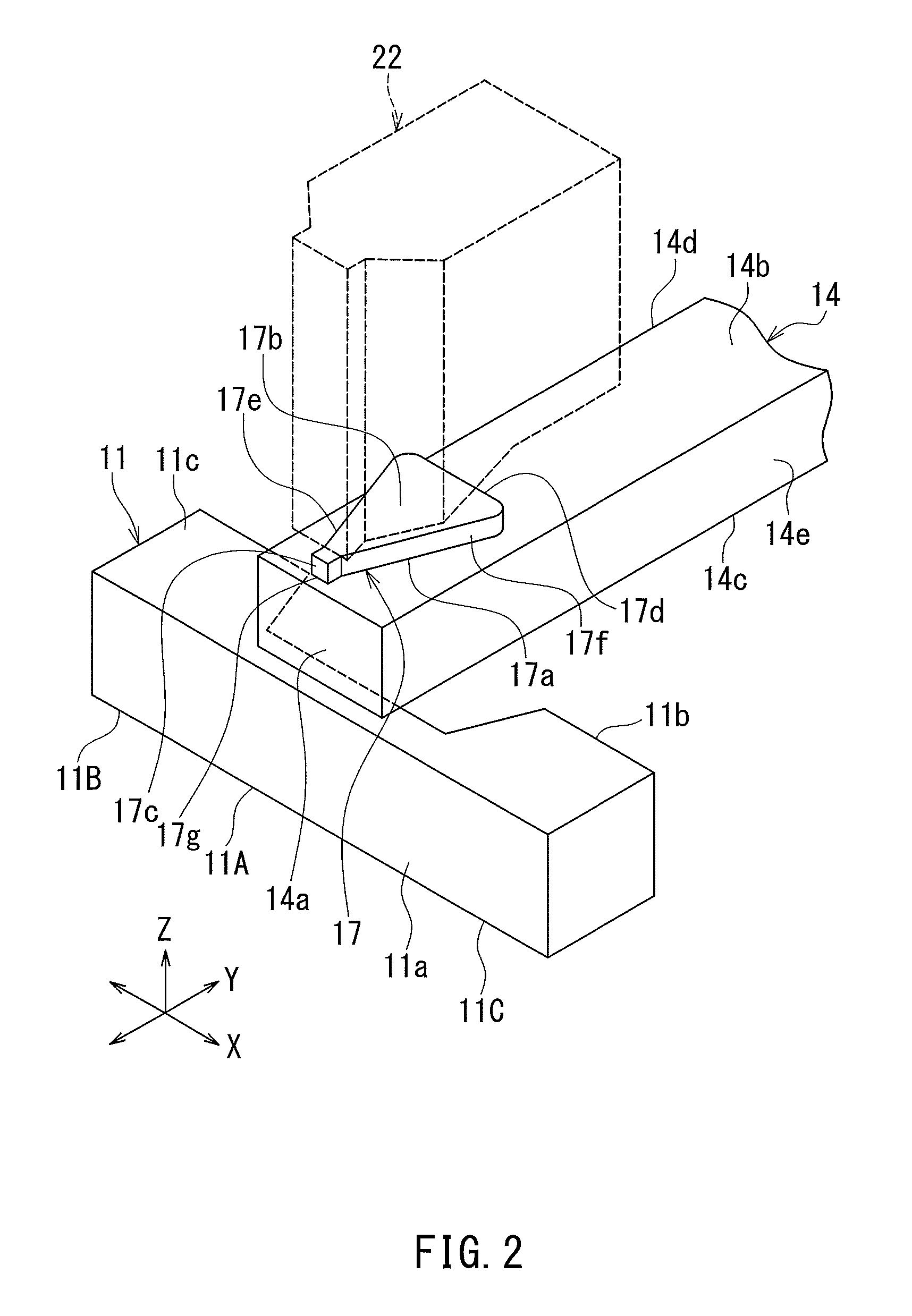
[0045]Preferred embodiments of the present invention will now be described in detail with reference to the drawings. First, reference is made to FIG. 1 to FIG. 6 to describe the configuration of a thermally-assisted magnetic recording head according to a first embodiment of the invention. FIG. 1 is a perspective view showing the main part of the thermally-assisted magnetic recording head. FIG. 2 is a perspective view showing a part of FIG. 1. FIG. 3 is a cross-sectional view showing the configuration of the thermally-assisted magnetic recording head. FIG. 4 is a front view showing the medium facing surface of the thermally-assisted magnetic recording head. FIG. 5 is a plan view showing a first layer of a coil of the present embodiment. FIG. 6 is a plan view showing a second layer of the coil of the present embodiment.

[0046]The thermally-assisted magnetic recording head according to the present embodiment is for use in perpendicular magnetic recording, and is in the form of a slider ...

second embodiment

[0104]A thermally-assisted magnetic recording head according to a second embodiment of the invention will now be described with reference to FIG. 7 to FIG. 11. FIG. 7 is a perspective view showing the main part of the thermally-assisted magnetic recording head. FIG. 8 is a front view showing the main part of the thermally-assisted magnetic recording head. FIG. 9 is a cross-sectional view showing the configuration of the thermally-assisted magnetic recording head. FIG. 10 is a front view showing the medium facing surface of the thermally-assisted magnetic recording head. FIG. 11 is a plan view showing a part of the thermally-assisted magnetic recording head.

[0105]The configuration of the thermally-assisted magnetic recording head according to the present embodiment differs from that of the head according to the first embodiment in the following ways. The thermally-assisted magnetic recording head according to the present embodiment includes a shield 40 formed of a magnetic material, ...


PUM

PropertyMeasurementUnit
distanceaaaaaaaaaa
temperaturesaaaaaaaaaa
widthaaaaaaaaaa

Abstract

A return path section includes first and second yoke portions and first, second and third columnar portions. The first and second yoke portions and the first columnar portion are located on the front side in the direction of travel of a recording medium relative to a waveguide core. The second and third columnar portions are located on opposite sides of a plasmon generator and connected to a shield. The first yoke portion connects a main pole to the first columnar portion. The second yoke portion connects the first columnar portion to the second and third columnar portions. A coil is wound around the first columnar portion. A heater and an expansion layer are located on the rear side in the direction of travel of the recording medium relative to the core.

Description

BACKGROUND OF THE INVENTION[0001]1. Field of the Invention[0002]The present invention relates to a thermally-assisted magnetic recording head for use in thermally-assisted magnetic recording in which a recording medium is irradiated with near-field light to lower the coercivity of the recording medium for data writing.[0003]2. Description of the Related Art[0004]Recently, magnetic recording devices such as magnetic disk drives have been improved in recording density, and thin-film magnetic heads and recording media of improved performance have been demanded accordingly. Among the thin-film magnetic heads, a composite thin-film magnetic head has been used widely. The composite thin-film magnetic head has such a structure that a read head unit including a magnetoresistive element (hereinafter, also referred to as MR element) for reading and a write head unit including an induction-type electromagnetic transducer for writing are stacked on a substrate. In a magnetic disk drive, the thi...

Claims


Application Information

Patent Timeline
Patent Type & Authority Patents(United States)
IPC IPC(8): G11B5/00G11B5/127G11B5/48G11B5/31G11B5/60
CPCG11B5/314G11B5/1278G11B5/4866G11B5/607G11B5/6076G11B5/6088G11B2005/0021
Inventor SASAKI, YOSHITAKAITO, HIROYUKITANEMURA, SHIGEKISATO, KAZUKIARAKI, HIRONORIFUJII, RYUJI
Owner HEADWAY TECH INC
Why Eureka
Try Eureka