Illumination device and observation device

a technology of observation device and illumination device, which is applied in the field of illumination device and observation device, can solve the problems of poor contrasting of phase objects, additional problems, and the “red reflex” does not appear uniformly bright over the patient's pupil, and achieves the effect of little structural complexity

Active Publication Date: 2013-09-03
CARL ZEISS MEDITEC AG
View PDF15 Cites 2 Cited by
  • Summary
  • Abstract
  • Description
  • Claims
  • Application Information

AI Technical Summary

Benefits of technology

[0016]Starting from the last-referred art, the object of the present invention is to further develop an illumination device and an observation device of the type named initially, in such a way that the illumination device can be introduced with little structural complexity even in those cases where only a small structural space is available.
[0020]In comparison with the solution known from the prior art, the one-stage illumination according to the invention dispenses with a Köhler illumination and thus omits an imaging of a luminous-field diaphragm and an aperture diaphragm. In this way, the structural space necessary for the illumination device can be reduced. Also, the illumination device can be built in a structurally simple manner, which is of advantage in many cases.
[0035]In another configuration, the illumination device can advantageously have at least one optical element for avoiding stray light. This element may involve, for example, a diaphragm, which can be configured as a fixed or variable diaphragm.
[0042]As patterned illumination sources, OLEDs offer a good light efficiency and small structures without intermediate dark spaces. Depending on the desired lighting geometry, individual miniature light sources can be turned on and others can remain turned off. The filling factor is higher in OLEDs as opposed to LEDs, which means that a higher packing density can be provided. The use of a display of LEDs or OLEDs makes possible a programmable switching, and also, for example, the switching of different lighting modes that can be automated, without having to move mechanical components, such as, e.g., phase contrast rings, filters, reducers and similar components. Particularly suitable, for example, are white OLEDs, whose spectrum is determined by a mixture of organic molecules.

Problems solved by technology

This has the consequence, however, that the “red reflex” does not appear uniformly bright over the patient's pupil.
Additional problems may occur when the patient's pupil is small or in connection with the refraction of the patient's eye.
Tests with coaxial illumination in fact led to a good, homogeneous “red reflex”, but to a poor contrasting of phase objects, and thus previously have not proven suitable in practice.
In many cases, however, only a small structural space is present for the illumination device, so that an illumination optics unit, which is constructed according to the Köhler principle of illumination, cannot always be used.

Method used


Image

  • Illumination device and observation device
  • Illumination device and observation device
  • Illumination device and observation device

Examples


Embodiment Construction

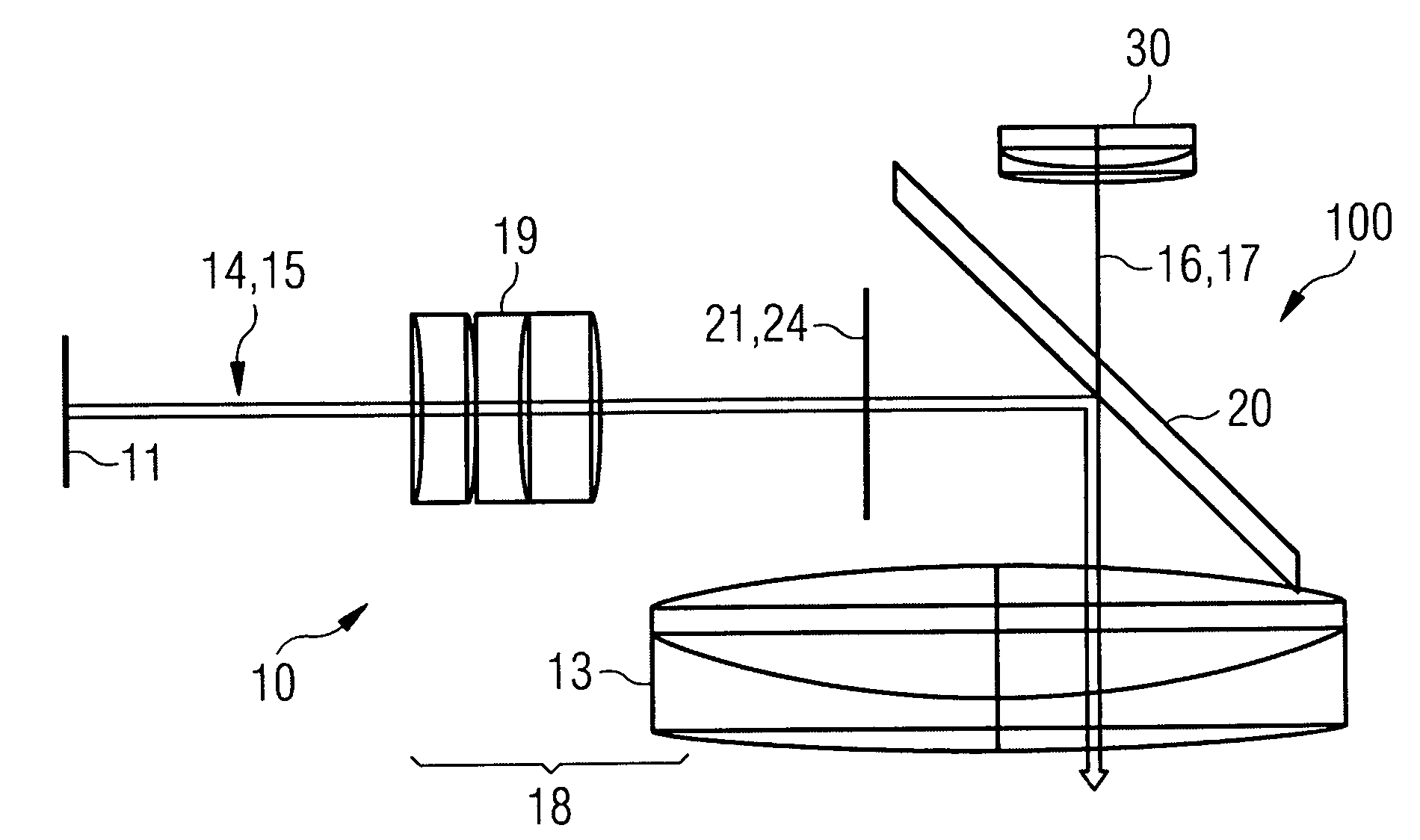
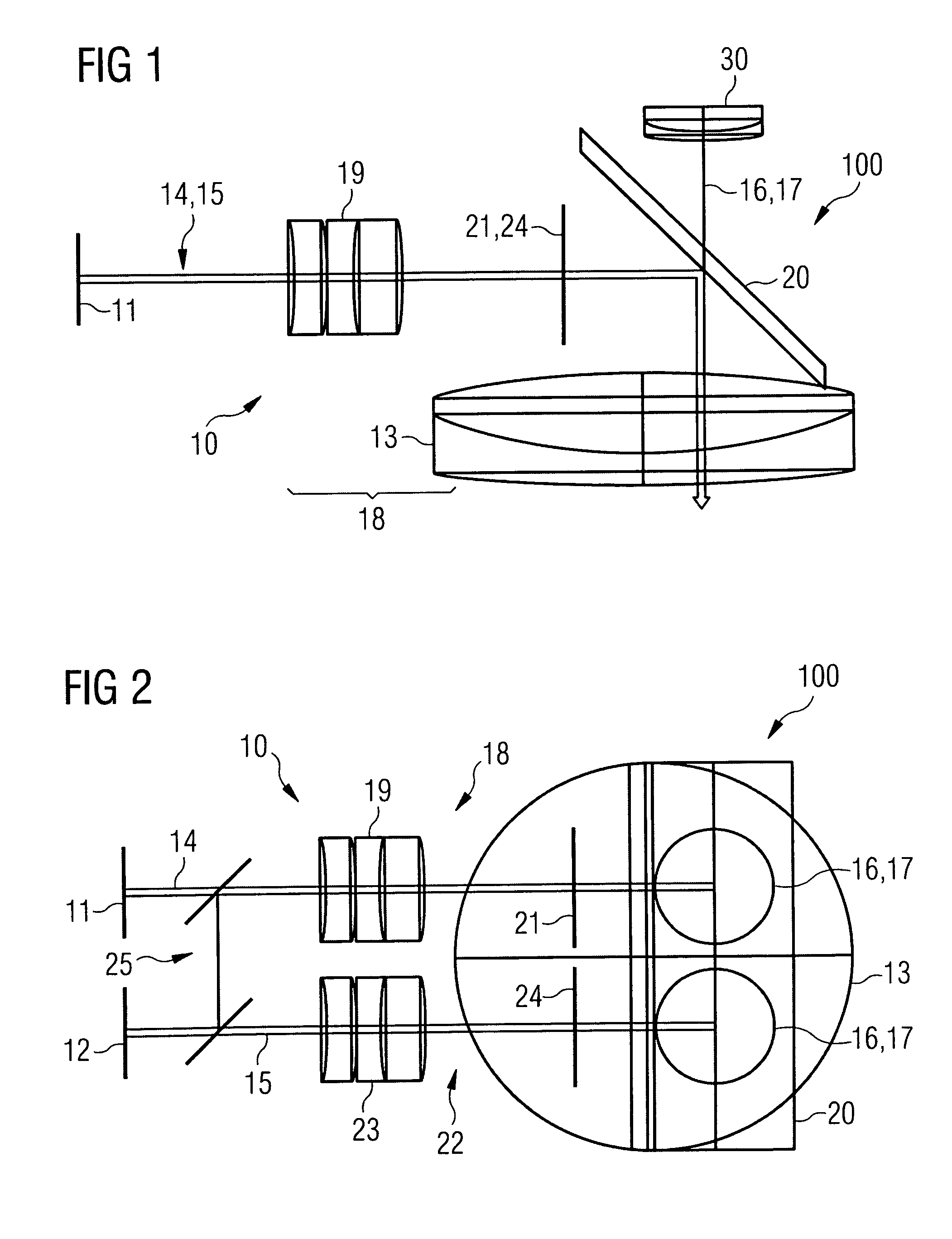
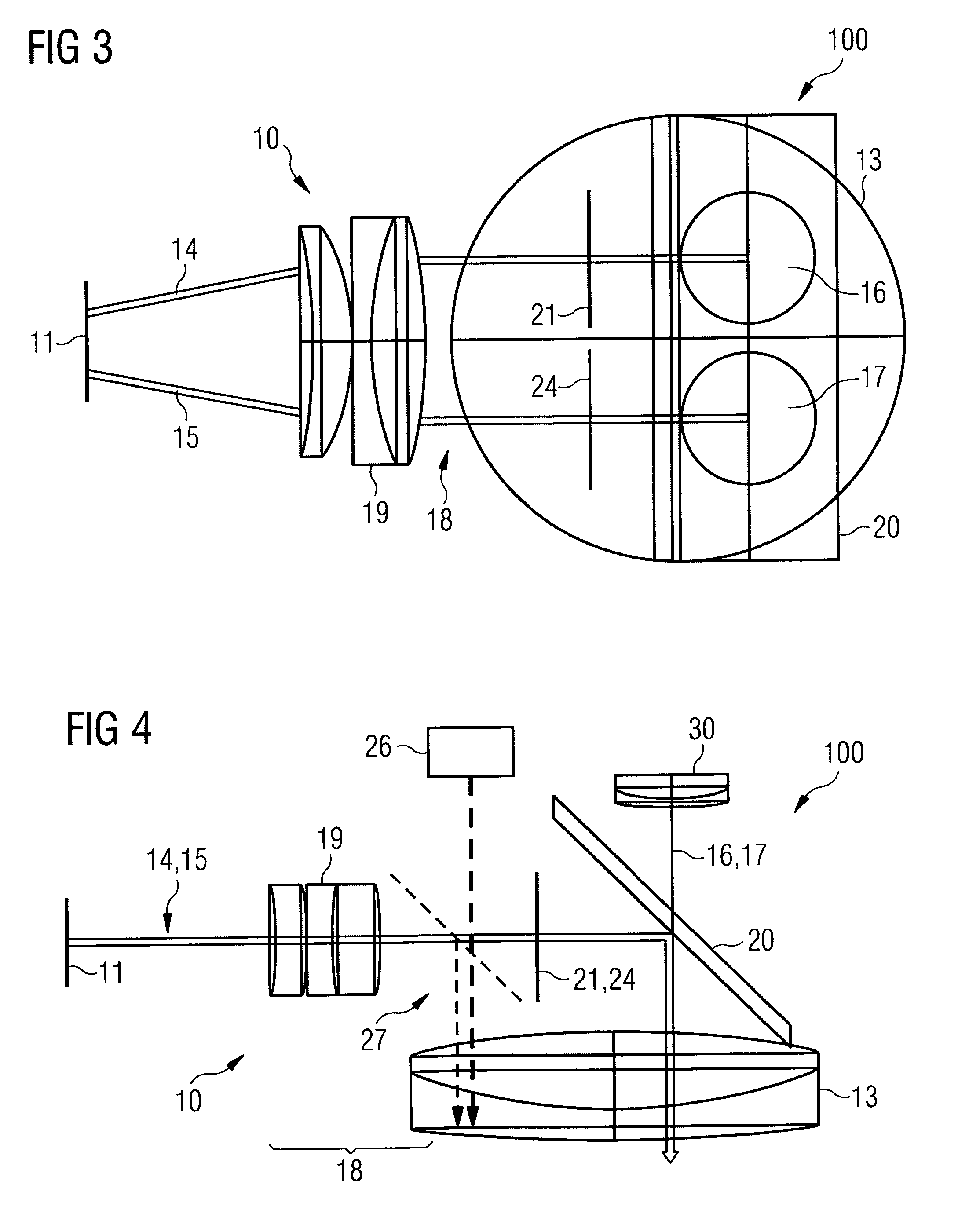
[0058]Shown in each of FIGS. 1 to 7 is an illumination device 10, which is used as an illumination device in an operating microscope 100, particularly in an ophthalmologic observation device, preferably in an operating microscope designed for cataract extraction. Operating microscope 100 has two observation beam paths 16, 17, in which additional optical elements 30 can be provided, but which will not be discussed in more detail in the following.

[0059]Embodiment examples are shown in the figures, in which the illumination device has an objective element 13, which is also shown simultaneously as the principal objective of operating microscope 100.

[0060]As is shown in FIGS. 1 and 2, illumination device 10 first provides at least one light source 11 for generating at least one illumination beam path 14, 15 with at least one illumination beam bundle, which will be superimposed coaxially with at least one observation beam path 16, 17 or observation beam bundle. A coaxial illumination will...


PUM


Abstract

An illumination device (10) is described for an observation device (100) having one, two or more observation beam paths (16, 17), each with at least one observation beam bundle, particularly for an operating microscope, the illumination device having at least one light source (11, 12) for producing at least one illumination beam path (14, 15) with at least one illumination beam bundle for illuminating an object to be observed, in particular, an eye to be observed, the illumination device (10) having at least one illumination optics unit, which has a collector (18, 22), and the at least one illumination beam path (14, 15) or the at least one illumination beam bundle running coaxially to an observation beam path (16, 17) or observation beam bundle. In order to create an illumination device that can be introduced with little structural complexity even in those cases where only a small structural space is available, it is provided according to the invention that light source (11, 12) lies in the front focal point of collector (18, 22) and is imaged on the fundus of the eye to be observed. In addition, a correspondingly improved observation device (100) is described.

Description

CROSS-REFERENCE TO RELATED APPLICATIONS[0001]The present application claims the benefit under 35 U.S.C. 119(e) of U.S. Provisional Patent Application No. 61 / 203,090, filed Dec. 18, 2008, the disclosure of which is incorporated herein by reference.BACKGROUND OF THE INVENTION[0002]The present invention relates first to an illumination device for an observation device according to the preamble of patent claim 1. In addition, the invention relates to an observation device according to the preamble of patent claim 17.[0003]For example, an observation device may involve an operating microscope. In particular, the observation device can be designed as an ophthalmologic operating microscope, which is utilized, for example, for a special application in eye surgery, i.e., cataract surgery.[0004]In the case of cataract surgery, a lens of the eye—which is clouded, for example, due to the cataract—is replaced by an artificial lens.[0005]The lens of an eye is found inside a thin envelope, the so-...

Claims


Application Information

Patent Timeline
Patent Type & Authority Patents(United States)
IPC IPC(8): A61B3/10A61B3/14A61B3/00G02B27/02
CPCA61B3/12A61B3/13
Inventor MERZ, FRANZHOEGELE, ARTURREIMER, PETER
Owner CARL ZEISS MEDITEC AG
Why Eureka
Try Eureka