
Adjustable steering column for a motor vehicle
a technology for motor vehicles and steering columns, applied in steering controls, vehicle mounted steering controls, vehicle safety arrangments, etc., can solve the problem of only tight connection, and achieve the effect of reducing the risk of actuation levers
- Summary
- Abstract
- Description
- Claims
- Application Information
AI Technical Summary
Benefits of technology
Problems solved by technology
Method used
Image

Examples
first embodiment
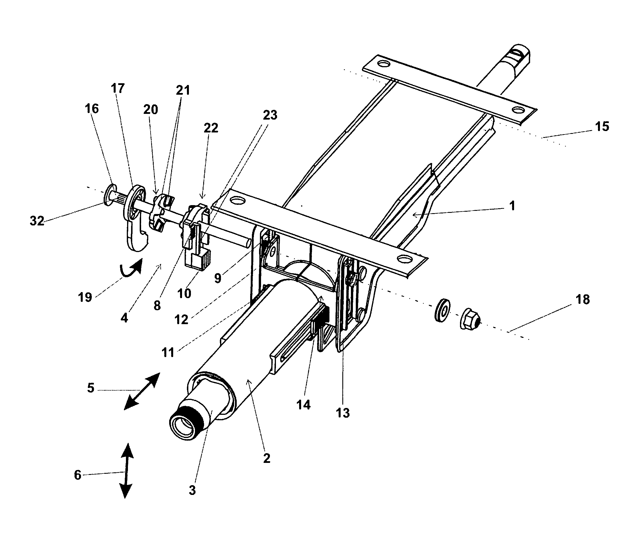
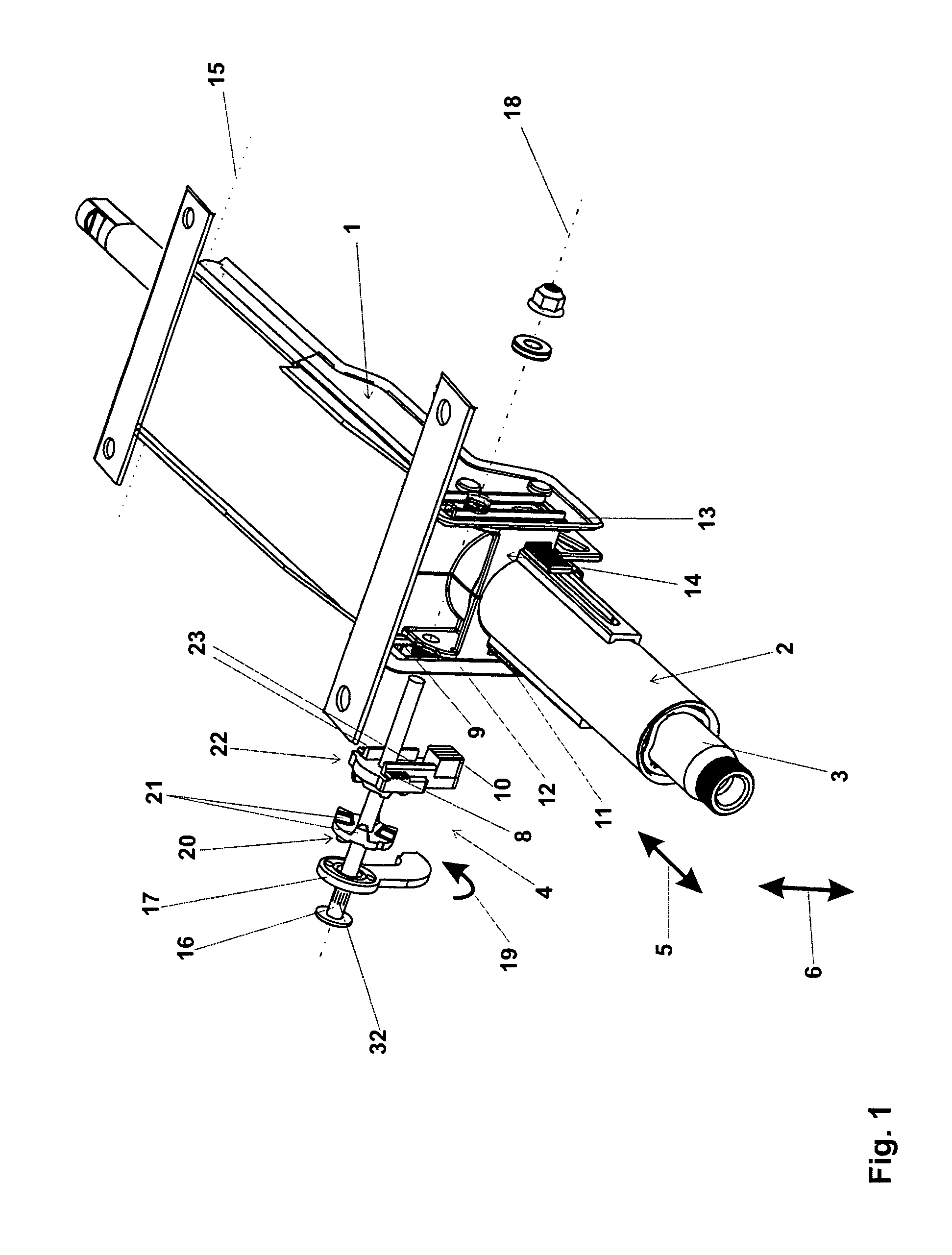
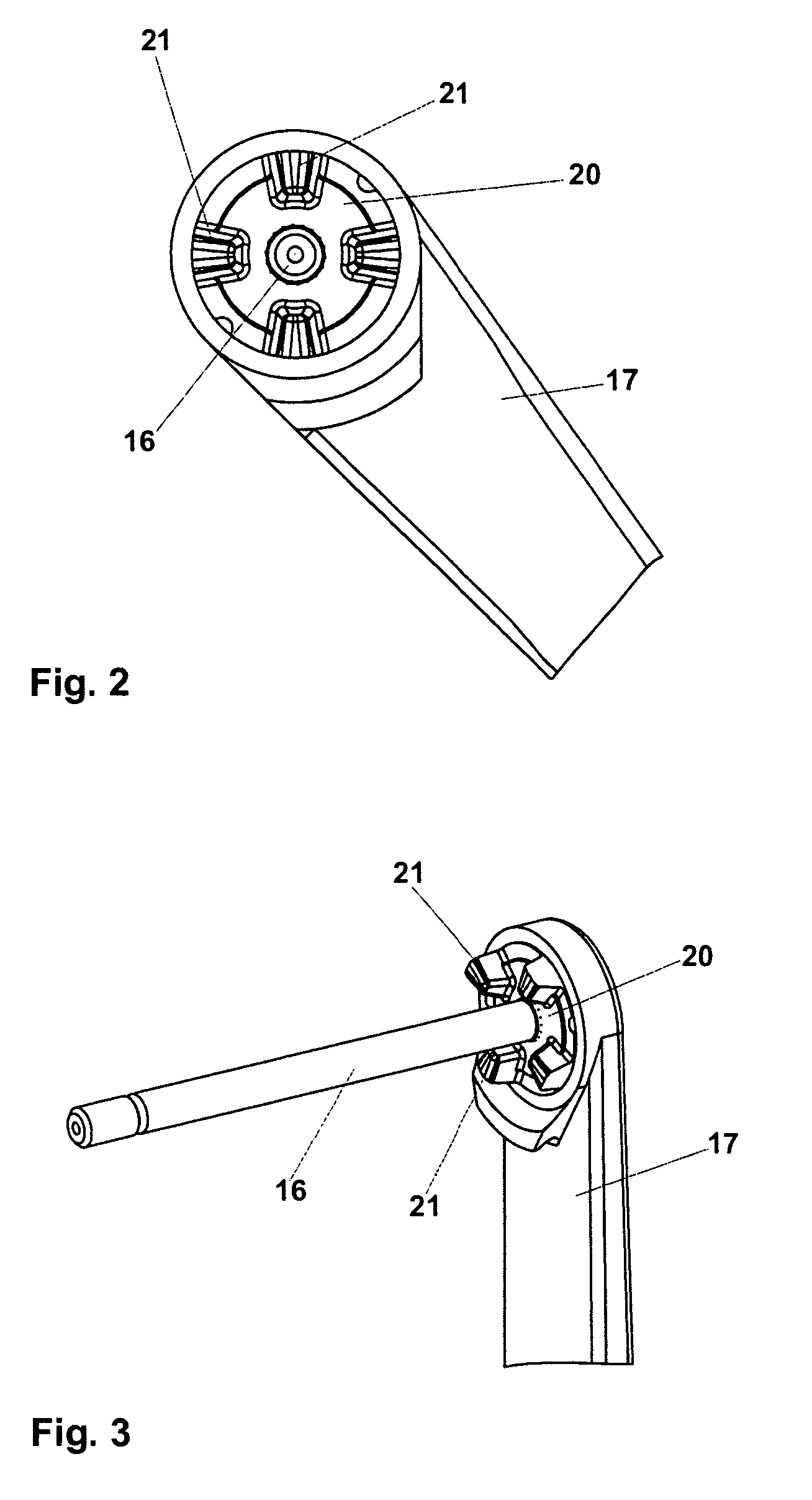
[0034]the invention will be explained in the following section in conjunction with FIGS. 1 to 11. The steering column comprises a support unit 1, which is connectable to the chassis of the motor vehicle, and a setting unit 2, which rotatably bearing supports a section of the steering spindle 3 adjoining the steering wheel-side end of the steering column. The setting unit 2 is realized in the form of a jacket tube.
[0035]In the opened state of a clamping mechanism 4, the setting unit 2 is displaceable in the longitudinal direction 5 of the steering column (=in the direction of the longitudinal axis of the steering spindle 3) for a length adjustment of the steering column and in the setting direction 6 for a height or inclination adjustment of the steering column with respect to the support unit 1. In the closed state of the clamping mechanism 4, the set position of the setting unit 2 is secured in position with respect to the support unit 2. To secure the adjustment, for example, as d...
second embodiment
[0057]the invention, which differs in view of the overcoming of the form closure between the actuating lever 17 and the clamp element 20 in the event of a crash, will be explained in the following. During normal operation, thus as long as the limit value of the torque acting between the actuating lever 17 and the clamp element 20 has not been exceeded, this embodiment is realized as depicted in FIGS. 1 to 10 and previously described. When the limit value is exceeded, however, the shearing-off of the connection studs 25 does not occur, as is depicted in FIG. 11. However, the form closure blocking the turning out of position of the actuating lever 17 with respect to the clamp element 20 is rather overcome through material reformation, as is depicted in FIG. 12. The recesses 26, into which the connection studs 25 project in normal operation and are retained under form closure, here represent expanded regions of a groove-form guide track 28 for the particular connection studs 25.
[0058]I...
PUM
 Abstract
Description
Claims
Application Information