Apparatus and method for turning racks

a technology for turning racks and accessories, applied in the direction of metal rolling arrangements, instruments, material analysis, etc., can solve the problems of specimen slides falling out of the rack or experiencing uncontrolled movement, specimen slides falling out of the rack, and inability to turn or tilt the magazine frame, etc., to achieve the effect of improving the reliability and low-load of the turning operation, and improving the accuracy of the turning operation

Active Publication Date: 2014-03-04
LEICA BIOSYST NUSSLOCH
View PDF16 Cites 4 Cited by
  • Summary
  • Abstract
  • Description
  • Claims
  • Application Information

AI Technical Summary

Benefits of technology

[0011]This object is achieved according to the present invention in that the rotation axis of the rack extends obliquely with respect to the longitudinal axis of the horizontally oriented rack, so that the rack can be pivoted back and forth between the first and the second position by means of a 180-degree rotation around the rotation axis. This enables an easy automatic reorientation of the rack from the horizontal into the vertical position, two motions around two axes being combined into one motion around one axis. The first axis concerns the orientation from horizontal to vertical, the specimen not being accessible for the user at this state. The second axis concerns the rotation of the rack by 180°, by what the specimen become accessible for the user. As merely one axis of movement is necessary within the coverslipper, construction of the system is simplified. The racks can be introduced into the system in a coverslipper as well as in a stainer.
[0015]The turning / tilting device according to the invention for racks with specimen slides accommodated therein, ensures that the specimen slides disposed in the rack are moved from a vertical to a horizontal position, thereby keeping the specimen slides from falling out of the rack or from moving uncontrollably when the rack is turned. This would be the case when the rack is merely tilted by 90°.
[0016]The rack turner according to the invention can be used in both stainers and coverslippers. For example, if a rack is introduced the wrong way around into the system by the laboratory worker on duty, the incorrect positioning can be corrected. A corresponding transport apparatus can check the orientation of the rack and authorize a reorientation. Stainers and coverslippers can be made more reliable in terms of processing, such that a simple apparatus corrects human errors.
[0017]According to a preferred embodiment of the invention, the rotation axis of the rack is inclined 45 degrees with respect to the longitudinal axis of the horizontally oriented rack. When the rotation axis in further development of the invention's concept extends through the physical center of gravity of the rack, only a small drive force is sufficient for the rotary motion. The result of turning at the center of gravity is that no tilting moments occur, making the turning operation particularly reliable and low-load.
[0018]According to a further advantageous embodiment of the invention, at least one sensor is provided for sensing the rotary motion of the rack receptacle around the rotation axis. A sensor apparatus of this kind contributes considerably to process reliability.
[0019]The invention further encompasses a rack turning module having the rack turner according to the present invention, the rack receptacle being connected rotatably to a base element, and the base element comprising a drive system for rotating the rack receptacle around the rotation axis. As an independent and separately installable element for stainers or coverslippers, the module represents a simple and economical solution to human or technological errors, so that complex turning and pivoting systems can be omitted.

Problems solved by technology

Such rack arrangements, however, are not faced with the problem that the specimen slides can fall out of the rack or experience uncontrolled movement when the rack is turned.
Since the specimen slides are not fixed in the rack, there is always the danger that the specimen slides fall out of the rack when the rack is turned.
Turning or tilting of the magazine frame is, however, not possible.

Method used


Image

  • Apparatus and method for turning racks
  • Apparatus and method for turning racks
  • Apparatus and method for turning racks

Examples


Embodiment Construction

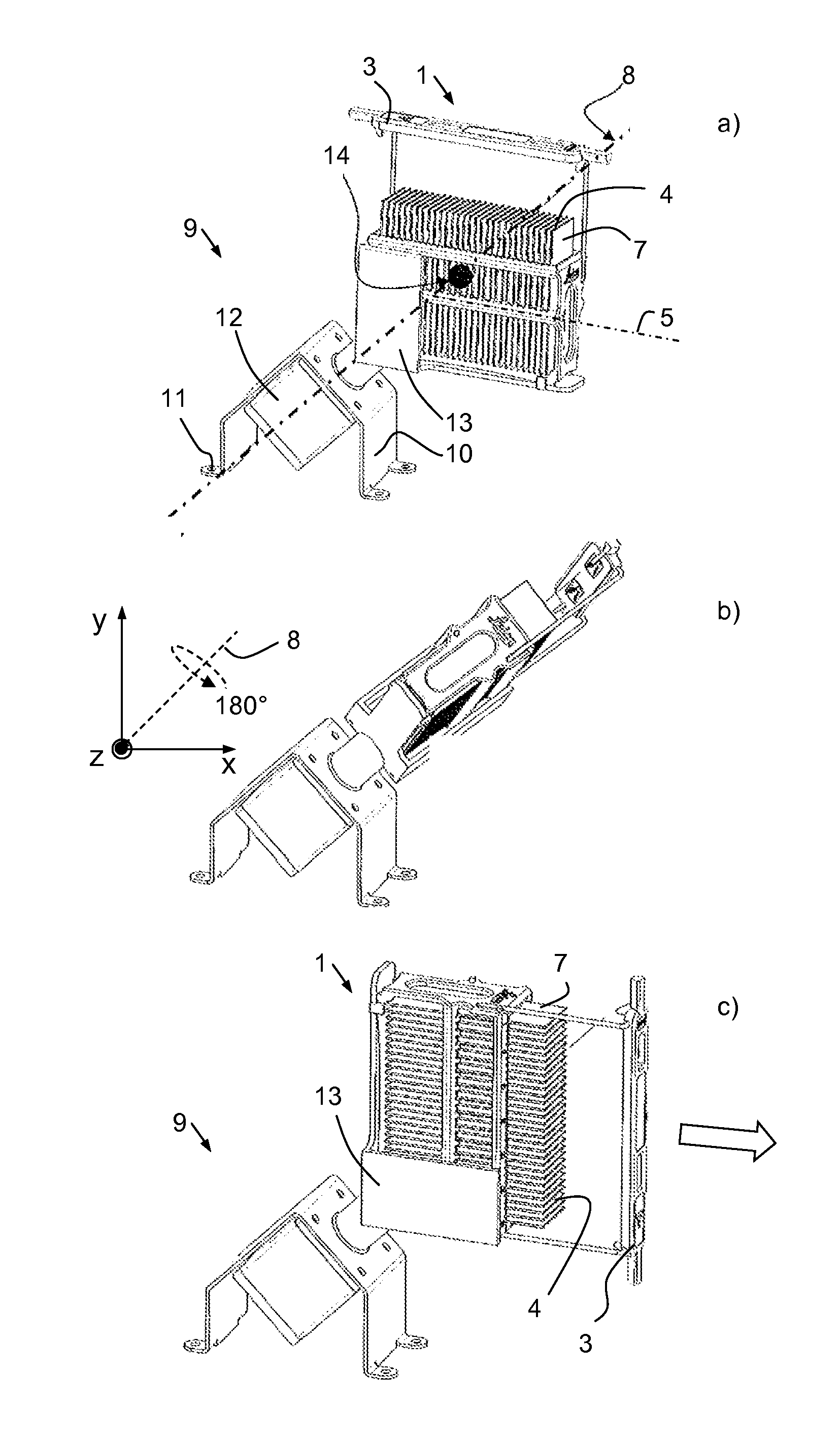
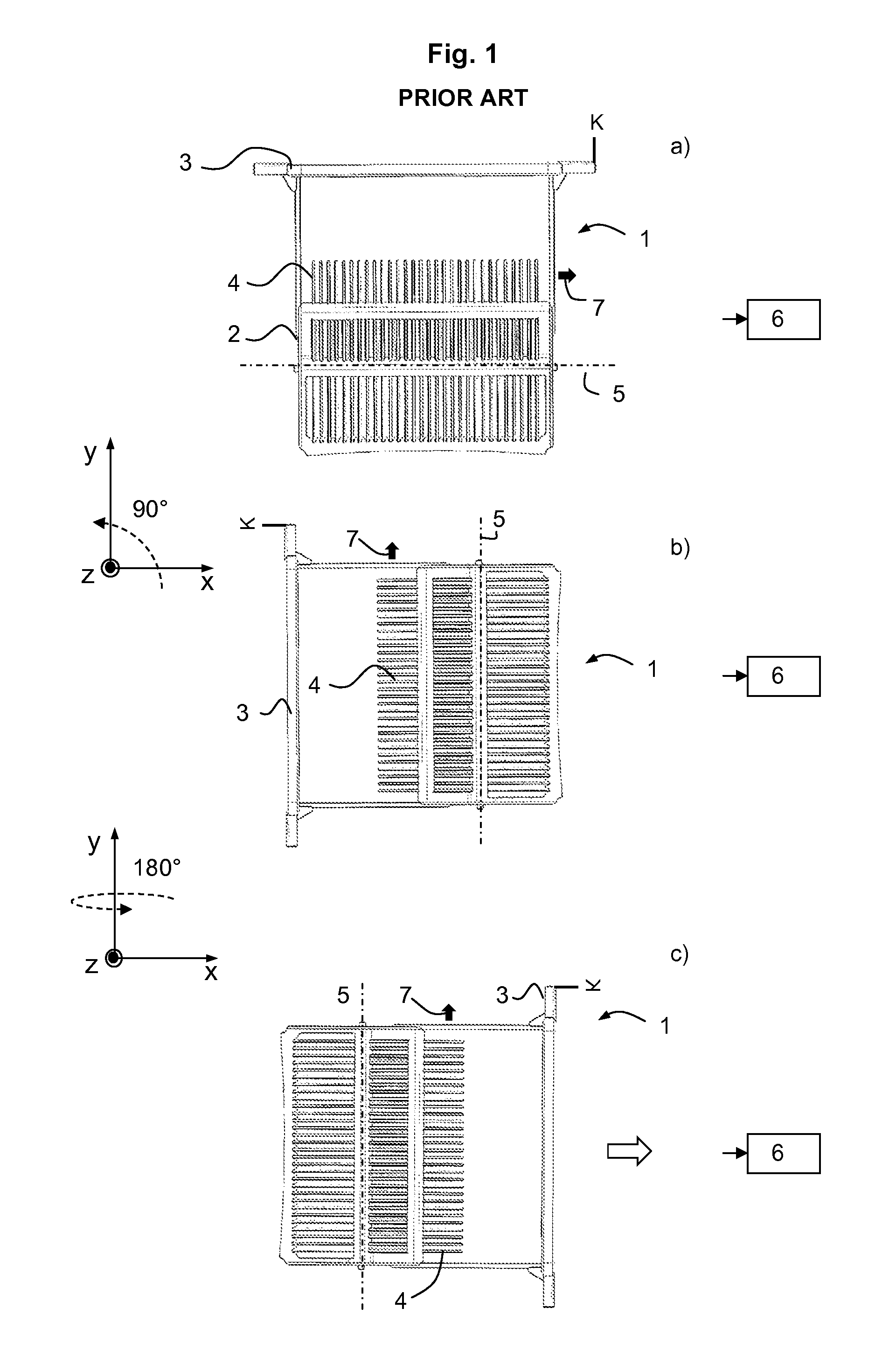
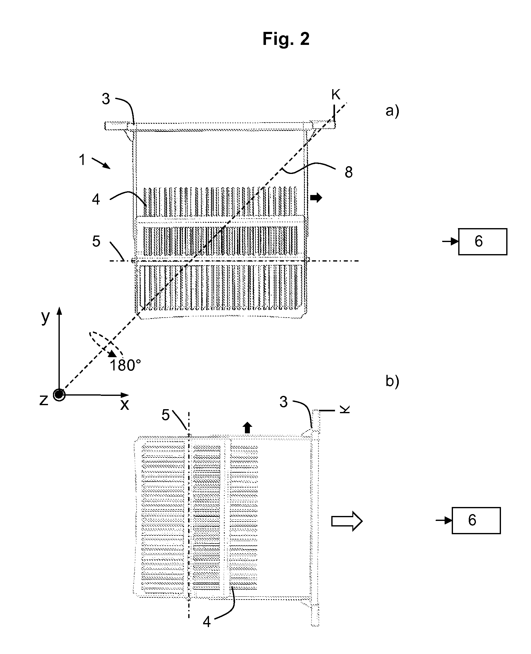
[0027]FIG. 1 shows a rack 1, used in stainers and coverslippers, in a variety of orientations a), b), and c). Rack 1 is made up substantially of a rack basket 2 and a rack bail 3, rack basket 2 being suspended from rack bail 3. A plurality of specimen slides 4 are inserted vertically in rack basket 2. Longitudinal axis 5 of rack basket 2 is oriented vertically. It is with rack 1 in this position that, inter alia, the staining process (in which rack 1 is immersed into stain containers) is carried out. The vertical position of specimen slides 4 is relevant for the subsequent coverslipping process, since it enables optimum runoff of the staining agent.

[0028]Shown in the Figure to the right of rack 1 is a black box 6 representing a coverslipping unit. Instead of a coverslipping unit, black box 6 can also stand for another processing station that requires a specific orientation of the rack. For the coverslipping process, specimen slides 4 must be removed from rack 1 and delivered to cove...


PUM

PropertyMeasurementUnit
rotation axisaaaaaaaaaa
rotationaaaaaaaaaa
gravityaaaaaaaaaa

Abstract

The invention relates to apparatuses for turning racks (1) for specimen slides (4), having a rack receptacle for at least one rack, the rack (1) being oriented in the rack receptacle horizontally in a first position such that specimen slides in the rack are arranged vertically next to one another relative to a longitudinal axis of the rack, and the rack receptacle being pivotable around a rotation axis (8) into a second position in which the rack (1) is oriented vertically. The rotation axis (8) of the rack (1) extends obliquely with respect to the longitudinal axis (5) of the horizontally oriented rack (1), so that the rack (1) can be pivoted back and forth between the first and the second position by means of a 180-degree rotation around the rotation axis (8).

Description

CROSS REFERENCE TO RELATED APPLICATIONS[0001]This application claims priority of German patent application number 10 2010 054 360.8 filed Dec. 13, 2010, the entire disclosure of which is incorporated by reference herein.FIELD OF THE INVENTION[0002]The invention relates to an apparatus for turning racks (“rack turners”) for specimen slides, for use in systems for preparing tissue samples for histological investigations, having a rack receptacle, wherein the longitudinal axis of the rack disposed in said rack receptacle is oriented horizontally in a first position and the specimen slides are arranged vertically next to one another relative to said longitudinal axis of the rack, and wherein the rack receptacle is pivotable around a rotation axis into a second position in which the rack is oriented vertically; and to a method for turning racks between the first and the second position.BACKGROUND OF THE INVENTION[0003]Apparatuses of this kind are used in particular in systems in which st...

Claims


Application Information

Patent Timeline
Patent Type & Authority Patents(United States)
IPC IPC(8): B65G7/08B65G47/22
CPCG02B21/34G01N1/312B01L9/52
Inventor WILKE, CHRISTIAN
Owner LEICA BIOSYST NUSSLOCH
Why Eureka
Try Eureka