Thoracic retractor

a retractor and thoracic technology, applied in the field of surgical retractors, can solve the problems that the tissue to be spread may not always be adequately held, and achieve the effect of flexible adaptability

Active Publication Date: 2014-05-06
KARL STORZ GMBH & CO KG
View PDF12 Cites 14 Cited by
  • Summary
  • Abstract
  • Description
  • Claims
  • Application Information

AI Technical Summary

Benefits of technology

[0008]Therefore, it is an object of the present invention to provide a surgical retractor which is more flexibly adaptable to a variety of surgical situations and / or types of surgical procedures.

Problems solved by technology

However, the tissues to be spread may not always be adequately held by blades which extend perpendicular or transverse to the directions of the holding arms and the rail.

Method used


Image

  • Thoracic retractor
  • Thoracic retractor
  • Thoracic retractor

Examples


Embodiment Construction

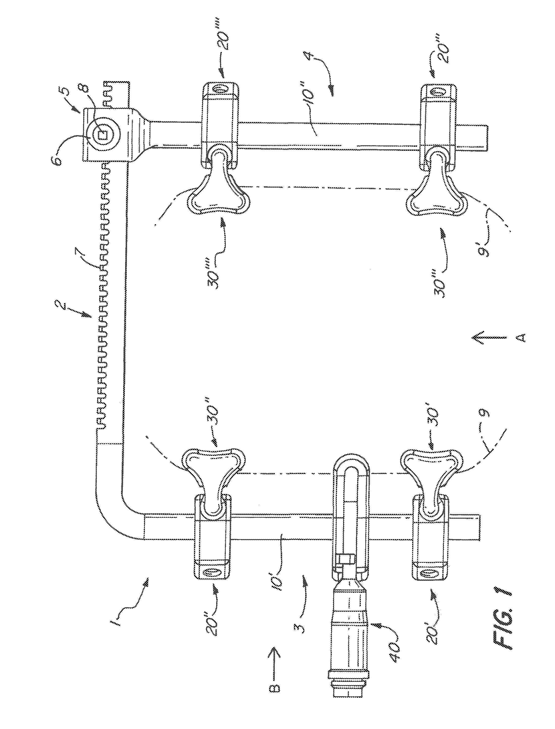
[0072]As shown in FIG. 1, an embodiment of a surgical retractor 1 comprises a rail 2, a first arm 3 and a second arm 4. The first arm 3 may be integral with the rail 2 or connected to the rail 2 in a rigid manner. The second arm 4 is connected to the rail 2 by a block 5 housing a drive mechanism 6. The drive mechanism engages with a toothed edge 7 of the rail 2 and can be operated by turning a drive shaft 8. The drive shaft 8 may exhibit a hand wheel or a detachable manipulation handle (not shown) for easier turning. The drive mechanism 6 permits adjustment of the distance between the first and second arms 3, 4. In particular, the retractor 1 can be spread or contracted by turning the drive shaft 8 in one or the other direction. Preferably, the drive mechanism 6 is configured in a self-blocking manner, i.e., the second arm 4 can be moved only by turning the drive shaft 8, but not by an external force acting upon the second arm 4 itself. Alternatively, fixation means might be provide...


PUM


Abstract

A surgical retractor has a rail, a first arm protruding from the rail at an angle, a second arm being movably mounted on the rail and extending substantially parallel to the first arm, and a multiplicity of holding elements mounted on the first and second arms. A holding element has a multi-axis joint for pivotably holding a blade for engaging tissue to be retracted. In this way, a most flexible surgical retractor is provided.

Description

CROSS-REFERENCE TO RELATED APPLICATIONS[0001]The present application claims priority of European patent application No. 10005960.9 filed on Jun. 9, 2010, the content of which is incorporated herein by reference.FIELD OF THE INVENTION[0002]The present invention relates to a surgical retractor for performing surgical interventions, in particular heart, thorax or spinal surgical interventions.BACKGROUND OF THE INVENTION[0003]In surgical interventions, it is frequently required to spread tissue in order to provide access to body structures situated below the tissue to be spread. In particular, in many heart, thorax and spinal surgeries, the sternum is divided longitudinally; the two parts of the sternum are then spread from each other, thus opening up the thorax in order to enable the surgeon to perform surgery inside or through the chest cavity.[0004]For spreading and holding tissue, surgical retractors are employed. Such a retractor usually comprises at least two tissue holding member...

Claims


Application Information

Patent Timeline
Patent Type & Authority Patents(United States)
IPC IPC(8): A61B1/32
CPCA61B2017/0046A61B17/0293A61B17/0206
Inventor ASSAKER, RICHARDTHOUEMENT, YANNBESSE, REGIS
Owner KARL STORZ GMBH & CO KG
Why Eureka
Try Eureka