Method and means for mounting wind turbines upon a column

a technology of supporting column and wind turbine, which is applied in the direction of machines/engines, renewable energy generation, greenhouse gas reduction, etc., can solve the problems of no human, the height of the machinery is the most significant factor in producing casualties, and the method is too cumbersome to be acceptable to the industry. , to achieve the effect of convenient protection

Inactive Publication Date: 2018-03-08
BOJANOVICH MATTEO
View PDF3 Cites 7 Cited by
  • Summary
  • Abstract
  • Description
  • Claims
  • Application Information

AI Technical Summary

Benefits of technology

[0023]A rapidly retractable wind turbine system can be easily protected from storm damage. A wind turbine column

Problems solved by technology

However, said methods have so far been viewed as too cumbersome to be acceptable to the industry.
While no human activity is totally safe, the height of the machinery has been the most significant fact

Method used


Image

  • Method and means for mounting wind turbines upon a column
  • Method and means for mounting wind turbines upon a column
  • Method and means for mounting wind turbines upon a column

Examples


Embodiment Construction

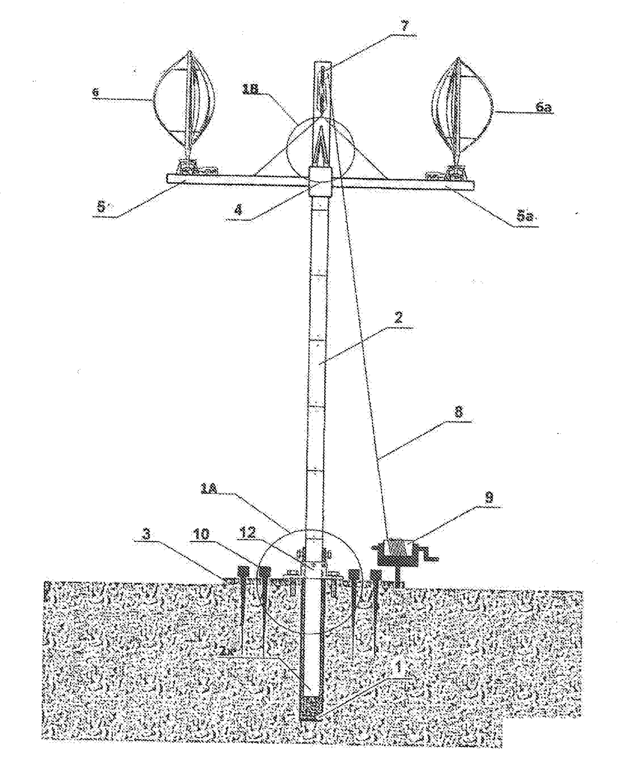
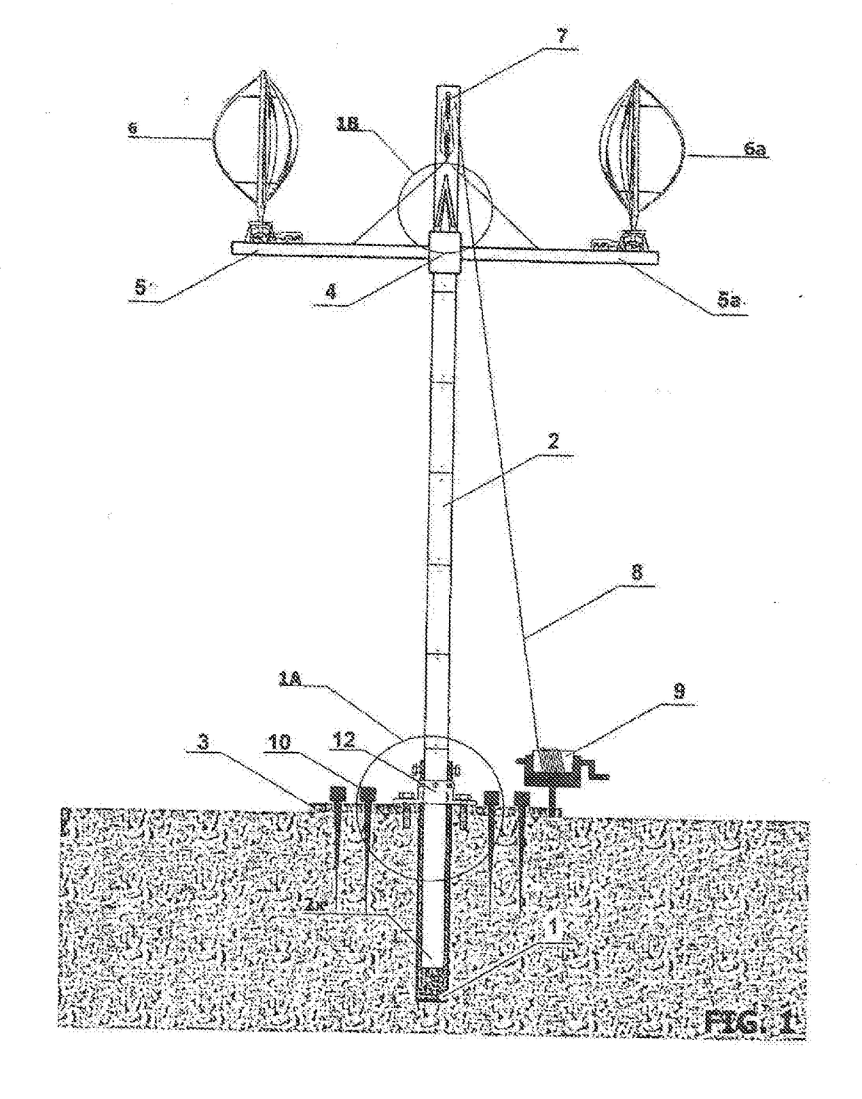
[0046]Referring to FIG. 1 (page 1 of 8), a side view shows a pipe 1, which was dropped into a hole drilled in the ground. A steel plate 3 with a central round opening is lowered over the part of pipe 1 that remains above ground.

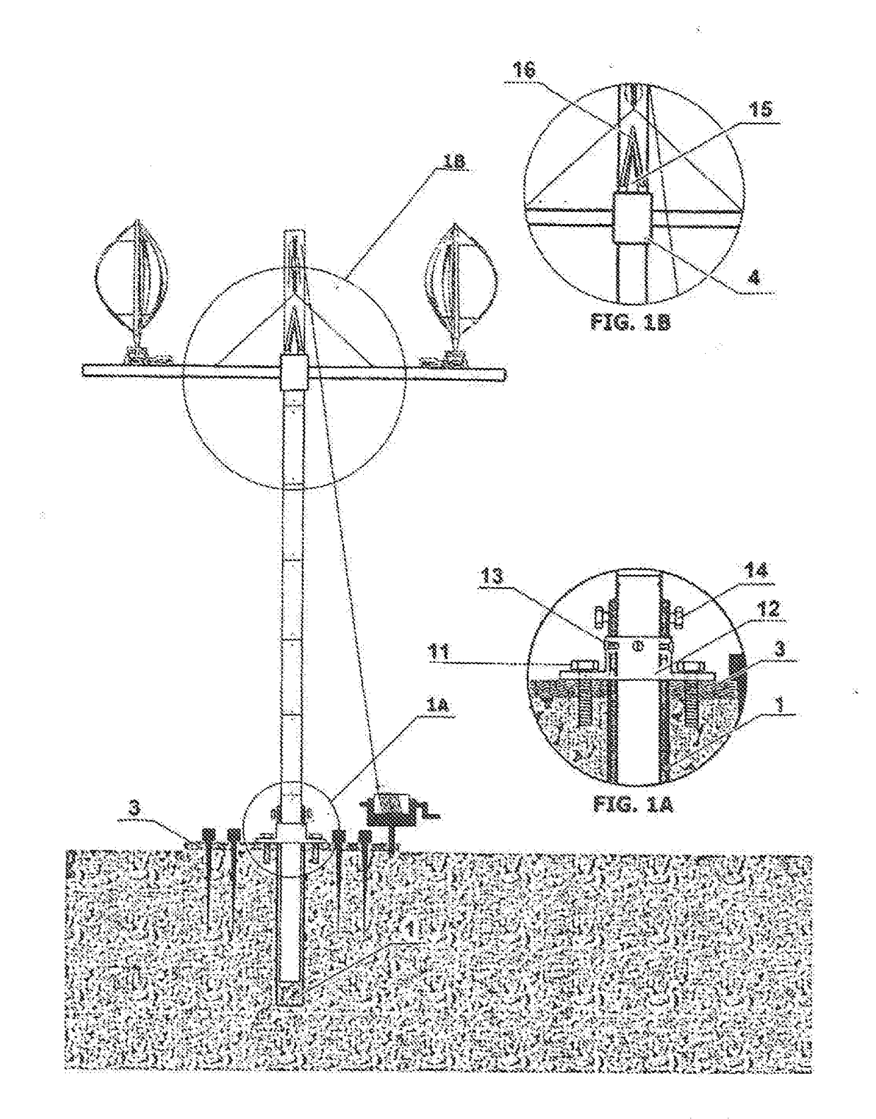
[0047]Referring to FIG. 1A (page 2 of 8), a side view shows a pipe 1 and plate 3 joined by coupling 12, the latter being bolted to 1 and 3 by means of screws 13 and 11. The function of screw 14 is to prevent eventual rotation of column 2 in the wind.

[0048]Referring to FIG. 1 (page 1 of 8), a side view shows the unit of pipe, coupling, and steel plate being stabilized by multiple spikes 10 which were inserted into holes in the steel plate 3 and hammered into the ground.

[0049]Referring to FIG. 1 (page 1 of 8), a side view shows how sections 5 and 5a are welded or bolted at a right angle to collar 4, said sections being formed by a section of pipe whose diameter is similar to that of pipe 1. Hence, this axis is formed by a combination of elements 4, 5, and 5a.

[...


PUM


Abstract

A variable level, relatively mobile wind power system consists of small, personal use wind turbines mounted upon an axis without need for a concrete mounting platform. As needed, the axis may be brought to the desired level upon a column and retracted to the ground for servicing. The entire wind power system can also be easily transferred to a different location.

Description

CROSS REFERENCE TO RELATED APPLICATION[0001]This application is a continuation-in-part of application Ser. No. 14 / 921,056, filed on Oct. 23, 2015, the disclosure of which is incorporated by reference herein.FIELD OF THE INVENTION[0002]The present invention relates to a method and means for mounting wind turbines at different levels of a supporting column.BACKGROUND OF THE INVENTION[0003]A major issue in regard to wind turbines is the likelihood of damage to the turbine and its tower during storms. The preferred solution has been to engineer constructions so massive as to be likely to withstand historically experienced storms. This solution has not eliminated catastrophic failure. Moreover, it resulted in prohibitive setup costs. Thus wind power, as currently in use throughout the world, involves very high start-up costs. Massive foundations and towers are required as well as cranes. As a result, wind power is not competitive with fossil fuel power generation systems.[0004]Wind speed...

Claims


Application Information

Patent Timeline
IPC IPC(8): F03D13/20F03D7/02
CPCF03D13/20F03D7/0268F05B2240/915E04H12/24E04H12/347F03D7/06F05B2240/913F03D13/22Y02E10/72Y02E10/728Y02E10/74
Inventor BOJANOVICH, MATTEO
Owner BOJANOVICH MATTEO
Why Eureka
Try Eureka