Conveying Device

a technology of conveying device and conveyor body, which is applied in the direction of mechanical conveyors, storage devices, conveyor parts, etc., can solve the problems of comparatively difficult control and low flexibility of structural design, and achieve the effects of increasing the operating efficiency of such plants, increasing the operating speed, and high throughpu

Inactive Publication Date: 2010-02-25
KRONES AG
View PDF91 Cites 7 Cited by
  • Summary
  • Abstract
  • Description
  • Claims
  • Application Information

AI Technical Summary

Benefits of technology

[0011]The conveying device according to the present disclosure can be used in a particularly advantageous manner in a bottle handling apparatus. The plastic bottle handling plants which are nowadays normally used and which comprise operations for producing, filling, closing, labelling and packing such plastic bottles, e.g. PET bottles, must be configured for high throughputs and the operating efficiency of such plants increases in proportion to an increase in their operating speed and a decrease in their susceptibility to failure. The conveying device according to the present disclosure offers the possibility of flexibly reacting e.g. to possible failures and of keeping the production losses caused by such failures as small as possible.
[0012]In addition to the mere buffer function, which is also given in the prior art, the conveying device according to the present disclosure allows a flexible use of the buffer, since both conveyors are connected to the buffer through a transfer site of their own, whereas the intermediate conveyor is fully removed from the conveying line when the buffer is in operation and resumes its conveying tasks only if the buffer is bridged during direct conveying. When the buffer is bridged, it can, however, be disabled whereby the amount of wear will be reduced to a significant extent.
[0013]The damage occurring in a bottle handling plant will be most severe when the blow-molding machine operates correctly, whereas some other device, downstream of the blow-molding machine, stands still. In order to prevent in this case that the preforms, which are contained in the blow-molding machine at the moment in question, can no longer be processed into finished bottles and have to be rejected consequently, the conveying device according to the present disclosure can advantageously be arranged between the blow-molding machine and an arbitrary one of the downstream machines, e.g. a filler, so that the blow-molding machine can finish the currently produced preforms and store them temporarily in the buffer. When the failure has been eliminated, the blow-molding machine can resume its operation, while the buffer is still being emptied, so that the downtime of the blow-molding machine will be reduced and so that the efficiency of the plant will be increased. If the buffer should be emptied more rapidly than it is being refilled, the intermediate conveyor can be switched on again at some time or other and the buffer can be deactivated, whereby its wear will be reduced.

Problems solved by technology

However, this structural design operates with a comparatively low flexibility and it only works when the conveying speeds are identical on both sides of the transfer star wheel.
In addition, the emptying of the buffer necessitates an inversion of the conveying direction, which is comparatively difficult to control.

Method used


Image

  • Conveying Device
  • Conveying Device
  • Conveying Device

Examples


Embodiment Construction

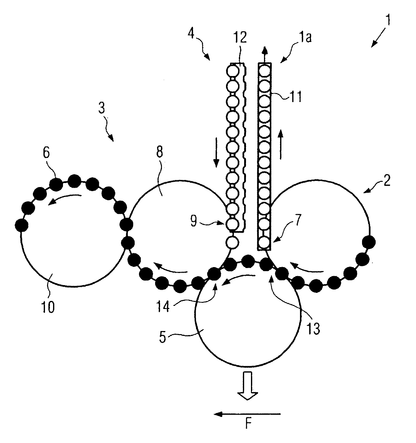
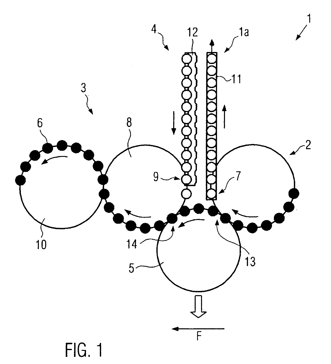
[0017]FIG. 1 shows in a highly schematic representation a first embodiment 1a of a conveying device 1 according to the present disclosure. The conveying device 1 comprises a first conveyor 2, a second conveyor 3, a buffer 4 and an intermediate conveyor 5, all of them configured for conveying objects 6, e.g. bottles and in particular PET bottles, which are passed through the conveying device 1 in a predetermined conveying direction F.

[0018]In the embodiment shown, the first conveyor 2 is configured as one of the conventional star wheels or rotors of the type used e.g. in handling plants for (plastic) bottles, in particular PET bottles, which convey the bottles in a condition in which they are suspended by the neck (neck handling). The first conveyor 2 is here shown only as a single conveyor, but, depending on the structural design of the plant, the first conveyor 2 may comprise a plurality of star wheels or rotors or other conveyors or it may be implemented directly as an outfeed mea...


PUM


Abstract

A conveying device for objects, in particular for bottles, having a first conveyor, a second conveyor and an intermediate buffer communicating with said first and second conveyors via a first transfer site. In order to increase the flexibility of such a conveying device, the first and second conveyors are connected to the buffer separately from one another via a respective first transfer site. Also, a switchable intermediate conveyor is provided, which bypasses the buffer and which is in conveying connection with the first and second conveyors via a respective second transfer site.

Description

[0001]The present application claims the benefit of priority of International Patent Application No. PCT / EP2007 / 005824, filed Jul. 2, 2007 which application claims priority of German Patent Application No. 10 2006 035 109.6, filed Jul. 29, 2006. The entire text of the priority application is incorporated herein by reference in its entirety.FIELD OF THE DISCLOSURE[0002]The disclosure relates to a conveying device for objects, in particular bottles, such as in beverage bottling operations.BACKGROUND[0003]Such a conveying device is known from DE 198 24 846. The known conveying device is arranged between a blow-molding machine used for producing plastic bottles and a filling machine for filling these bottles. The conveying device comprises a buffer for temporarily storing bottles as well as a large number of star wheels. In particular, a transfer star wheel is provided, which is used for charging and discharging the buffer as well as for directly conveying the bottles between the two ma...

Claims


Application Information

Patent Timeline
Patent Type & Authority Applications(United States)
IPC IPC(8): B65G47/32B65G37/00
CPCB65G2201/0244B65G47/5113
Inventor HAHN, WOLFGANG
Owner KRONES AG
Why Eureka
Try Eureka