Manufacturing Apparatus and Manufacturing Method of Lighting Device

a manufacturing method and technology of lighting devices, applied in the manufacture of electrode systems, manufacturing tools, electric discharge tubes/lamps, etc., can solve the problems of easy deterioration, extremely vulnerable light-emitting elements the emitted layer is extremely vulnerable to oxygen and moisture, so as to improve the use efficiency of materials and reduce manufacturing costs

Inactive Publication Date: 2010-09-23
SEMICON ENERGY LAB CO LTD
View PDF31 Cites 334 Cited by
  • Summary
  • Abstract
  • Description
  • Claims
  • Application Information

AI Technical Summary

Benefits of technology

[0014]With the use of the manufacturing apparatus of one embodiment of the present invention, film formation at high speed or successive film formation can be performed. Further, with the use of the manufacturing apparatus of another embodiment of the present invention, improvement in use efficiency of materials and reduction in manufacturing cost can be realized.

Problems solved by technology

A light-emitting layer (particularly a light-emitting layer including an organic compound) of these light-emitting elements is extremely vulnerable to oxygen and moisture and easily deteriorates.

Method used


Image

  • Manufacturing Apparatus and Manufacturing Method of Lighting Device
  • Manufacturing Apparatus and Manufacturing Method of Lighting Device
  • Manufacturing Apparatus and Manufacturing Method of Lighting Device

Examples


embodiment 1

[0044]In Embodiment 1, an example of a manufacturing apparatus provided with a deposition chamber is described with reference to drawings.

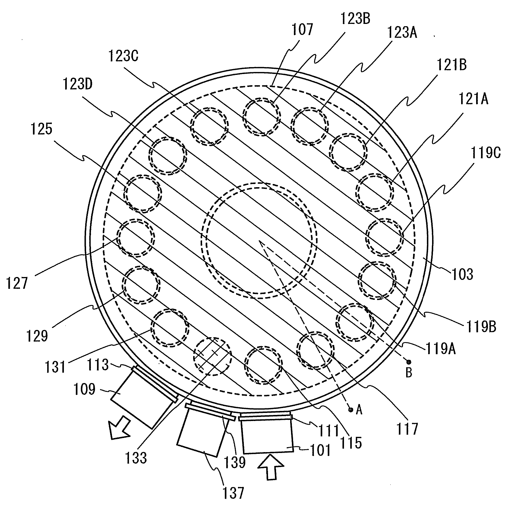
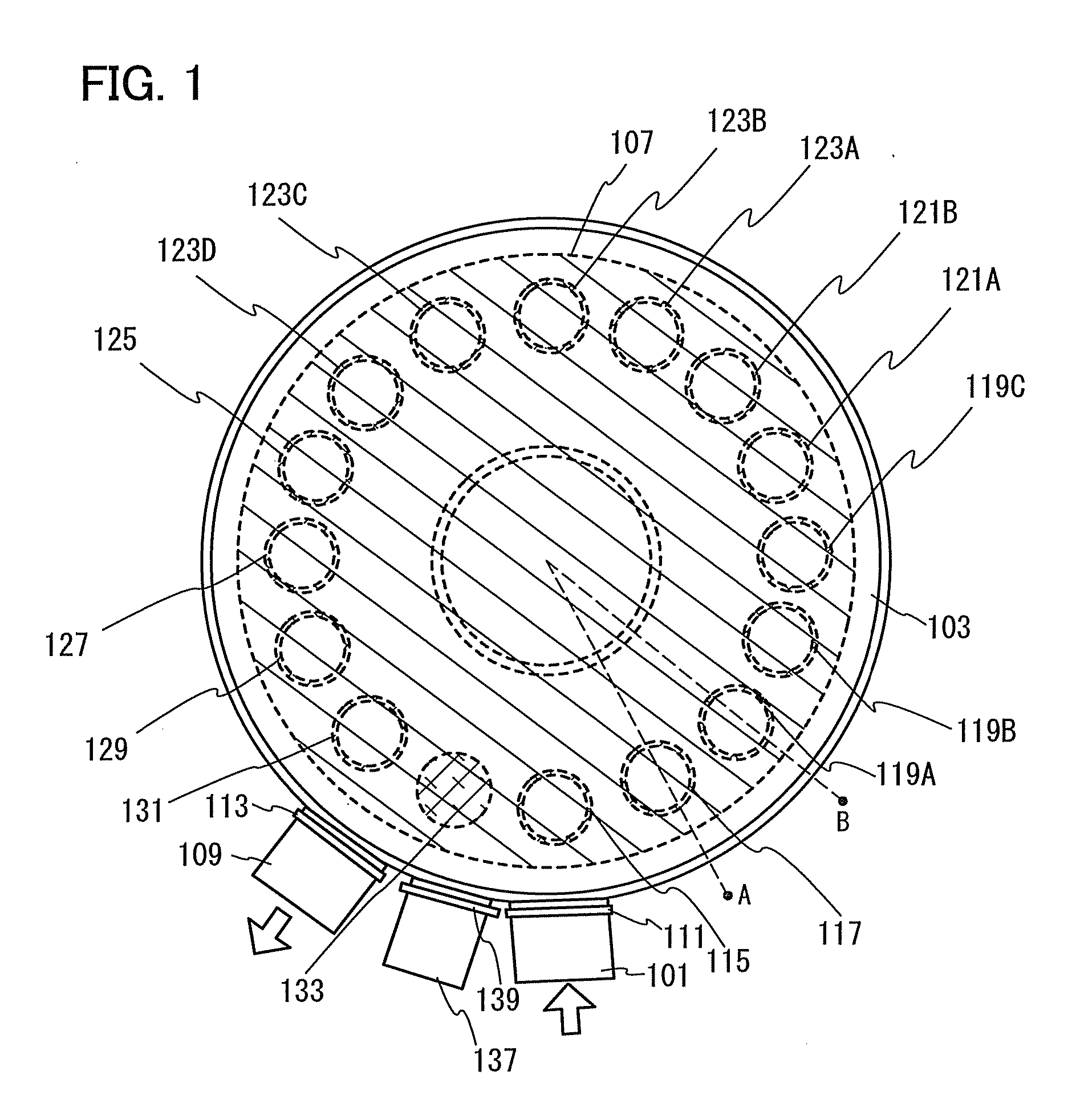
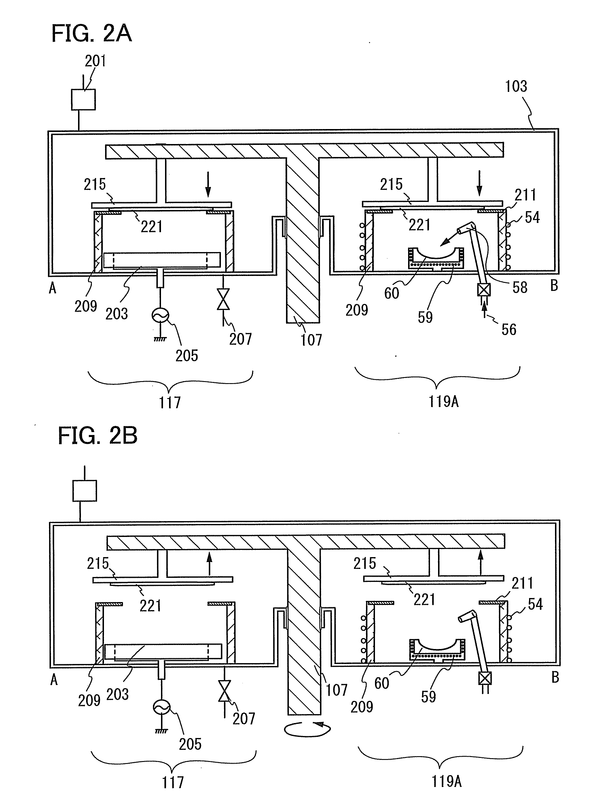
[0045]FIG. 1 is a schematic top view of the manufacturing apparatus of Embodiment 1. FIGS. 2A and 2B are cross-sectional views taken along line A-B in FIG. 1.

[0046]The manufacturing apparatus illustrated in FIG. 1 includes a first transfer chamber 101, a vacuum chamber 103, a second transfer chamber 109, and a third transfer chamber 137. In addition, in the vacuum chamber 103, deposition chambers 115, 117, 119A, 119B, 119C, 121A, 121B, 123A, 123B, 123C, 123D, 125, 127, 129, and 131, each of which is provided with a cylindrical protection plate, a sealing chamber 133, and a substrate transfer means 107 are provided. In FIG. 1, a substrate is transferred using the first transfer chamber 101 and the second transfer chamber 109. A sealing member of a light-emitting element is carried in using the third transfer chamber 137.

[0047]In this specification,...

embodiment 2

[0092]In Embodiment 2, an example of a deposition chamber provided in a manufacturing apparatus is described. Specifically, an example of a deposition chamber in which an organic material is formed by an evaporation method and a light-emitting unit or an intermediate layer of a light-emitting element is formed is described. FIG. 6 is a cross section of a schematic configuration diagram.

[0093]A deposition chamber 11 is placed in a vacuum chamber provided with a vacuum evacuation means, and is provided with an inert gas introduction means. For the vacuum evacuation means, a magnetic floating turbo molecular pump, a cryopump, or a dry pump is used. Ultimate degree of vacuum of the deposition chamber 11 can be set to 10−5 Pa to 10−6 Pa by the vacuum evacuation means. Further, an inert gas such as nitrogen or a rare gas is used as a gas to be introduced in order to prevent impurities from being introduced into the deposition chamber 11. A gas which is introduced into the deposition chamb...

embodiment 3

[0125]A procedure in which one substrate is processed is described in Embodiment 2. In Embodiment 3, a procedure in which a plurality of substrates is successively subjected to evaporation and an organic material is intermittently supplied to a container is described. Note that the same reference numerals are used for portions in common with those illustrated in Embodiments 1 and 2.

[0126]FIGS. 8A to 8C are timing charts each showing a procedure before and after evaporation on the substrate 10 and a procedure in which evaporation on a plurality of substrates is started. In FIG. 8A, the vertical axis represents electric power of the heater and the horizontal axis represents time. In FIG. 8B, the vertical axis represents a temperature of the container and the horizontal axis represents time. FIG. 8C shows a timing when the substrate is introduced into the deposition chamber 11 and a timing when the substrate is transferred to another treatment chamber (including a transfer chamber).

[01...


PUM

PropertyMeasurementUnit
diameteraaaaaaaaaa
diameteraaaaaaaaaa
temperatureaaaaaaaaaa

Abstract

A manufacturing apparatus of a lighting device, including a vacuum chamber, an exhaust system by which the vacuum chamber is set to a reduced-pressure state, and a transfer chamber from which a substrate is transferred to the vacuum chamber is provided. The vacuum chamber of the manufacturing apparatus includes a plurality of deposition chambers in which a first electrode, a first light-emitting unit including at least a light-emitting layer, an intermediate layer, a second light-emitting unit including at least a light-emitting layer, a second electrode, a sealing film are formed, and a substrate transfer means by which the substrate is sequentially transferred to the deposition chambers.

Description

BACKGROUND OF THE INVENTION[0001]1. Field of the Invention[0002]The present invention relates to a manufacturing apparatus of a lighting device, and particularly relates to a manufacturing apparatus provided with a deposition chamber which is used for formation of a light-emitting element, and a manufacturing method in which the manufacturing apparatus is used.[0003]2. Description of the Related Art[0004]In recent years, the development of elements in which thin films containing a compound that exhibits electroluminescence (EL) are used as light-emitting layers has advanced, and light-emitting elements using a variety of compounds have been proposed. These light-emitting elements cause a light emission phenomenon called electroluminescence (EL), in which holes and electrons are recombined in a light-emitting layer provided between an electrode (anode) for injecting holes and an electrode (cathode) for injecting electrons.[0005]A light-emitting element utilizing EL light emission is ...

Claims


Application Information

Patent Timeline
Patent Type & Authority Applications(United States)
IPC IPC(8): B05D5/12B05C11/00
CPCC23C14/12C23C14/228C23C14/246H01L51/56C23C14/568H01L51/001H01L51/5036C23C14/566B29C65/7844B29C65/7879B29C66/00145B29C66/452H10K71/164H10K50/125H10K71/00
Inventor YAMAZAKI, SHUNPEI
Owner SEMICON ENERGY LAB CO LTD
Why Eureka
Try Eureka