Device for locating epidural space while safeguarding against dural puncture through differential friction technique

a technology of differential friction and epidural space, which is applied in the direction of medical devices, intravenous devices, other medical devices, etc., can solve the problems of dural puncture, time-consuming and laborious, and difficulty in locating epidural space, so as to achieve precise location of epidural space, prevent accidental dural puncture, and achieve economic cost-effective and safe technique

Active Publication Date: 2014-05-06
B BRAUN MELSUNGEN AG
View PDF15 Cites 3 Cited by
  • Summary
  • Abstract
  • Description
  • Claims
  • Application Information

AI Technical Summary

Benefits of technology

[0021]The invention allows for pressurisation of the fluid in the syringe that leads to automatic injection of air or saline at the point of entry of the needle into the epidural space through differential friction at the tip of the needle, thereby causing the air or saline to be injected into the epidural space automatically.
[0022]One advantage of this invention is precise location of epidural space and simultaneous prevention of accidental dural puncture. Another objective of the invention is ergonomic, economically cost effective and safe technique.
[0023]The device of the invention is constructed on the technique of differential friction and has the advantage of applying the constant pressure on one single point i.e., on the piston of the syringe in attempt to inject air or saline. This results in two step-by-step actions i.e., simultaneous forward movement of the needle piercing through ligaments and building up of the pressure in the fluid contained the syringe, followed by simultaneous injecting of air or saline that pushes the dura further away and halting of the further movement of the needle even with a continuation of manual pressure on the piston of the syringe holding the wings which are located in a specialised way nearer to the hub of the needle.

Problems solved by technology

These techniques are not uncommonly associated with technical difficulties or complications.
The main disadvantage of this procedure is, it takes longer to establish the space and technically more demanding.
This is a safety concern as any slight inertial advancement of the hand may make the needle to move further, possibly causing dural puncture.

Method used


Image

  • Device for locating epidural space while safeguarding against dural puncture through differential friction technique
  • Device for locating epidural space while safeguarding against dural puncture through differential friction technique
  • Device for locating epidural space while safeguarding against dural puncture through differential friction technique

Examples


Embodiment Construction

[0048]A preferred embodiment of the invention will now be described with reference to the accompanying drawings to understand the technique and the construction of the device.

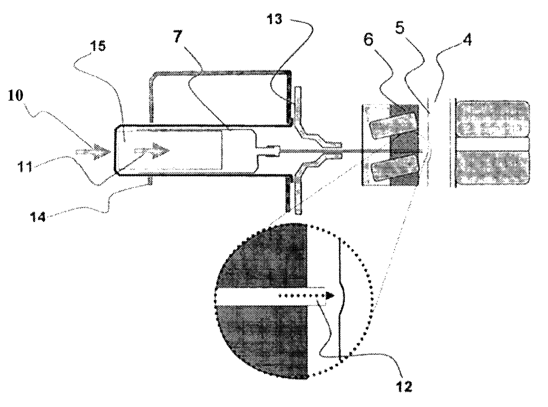
[0049]An illustrative embodiment of the device for locating the epidural space is depicted in FIGS. 13 & 14 wherein 7 is the barrel of the syringe, 15 is the piston of the syringe inside the barrel 7, 8 is the wings that are placed near the hub of the needle but not mounted, onto the needle 8, 14 is the frame connecting, the wings to the back of the piston where the manual forward force on the wings is transmitted. In the figures, 10 is the forward force on the piston which initially causes movement of the entire apparatus (9 in FIG. 13) when the needle tip is in the ligaments 6. When the needle tip opens into epidural space, the movement of the needle and the barrel is halted by the friction offered by ligaments. In the figures, 5 is the epidural space into which the needle tip opens and ejects the fluid throu...


PUM


Abstract

A device for locating a cavity within two walls including a syringe including a syringe piston slideable in a first syringe barrel for discharging air or fluid contained in the first syringe barrel on forward movement of the syringe piston into the cavity, the first syringe barrel being attached to a hub of a needle cannula; and a frame which at least in part encases the syringe and which is solely connected to the back of the syringe piston.

Description

CROSS REFERENCE TO RELATED APPLICATIONS[0001]This application is the U.S. national phase application of PCT International Application No. PCT / IN2009 / 000340, filed Jun. 12, 2009, which claims priority to Indian Patent Application No. IN 1491 / CHE / 2008 filed Jun. 19, 2008, the contents of such applications being incorporated herein by reference.FIELD OF THE INVENTION[0002]The present invention relates to an epidural space locating device which as well prevents dural puncture in the spinal column of vertebrates and, more particularly, of a modification in currently known epidural space locating systems which allows the anaesthetists to properly locate by injecting the air or saline into the epidural space in the process of injecting certain drugs and for passing a catheter for same purpose.BACKGROUND OF THE INVENTION[0003]In medical practice, identification of epidural space is required for therapeutic, anaesthetic and diagnostic procedures.[0004]The currently used techniques rely on hi...

Claims


Application Information

Patent Timeline
Patent Type & Authority Patents(United States)
IPC IPC(8): A61M5/00
CPCA61B17/3401
Inventor BETHI, RAVINDAR
Owner B BRAUN MELSUNGEN AG
Why Eureka
Try Eureka