Triac dimmable power supply unit for LED

a power supply unit and led technology, applied in the direction of semiconductor lamp usage, electric discharge lamps, discharge tubes/lamp details, etc., can solve the problems of slow startup of the pfc controller, the problem of the battery to turn off, and the problem of all firing angles, so as to reduce the current

Active Publication Date: 2014-05-13
HUIZHOU LIGHT ENGINE LTD
View PDF9 Cites 13 Cited by
  • Summary
  • Abstract
  • Description
  • Claims
  • Application Information

AI Technical Summary

Benefits of technology

[0022]In another aspect, the dimming slope control circuit makes the slope of a dimming curve of the triac dimmer steeper, such that a reduced amount of current is supplied to the one or more LEDs for a given firing angle of the triac dimmer.
[0030]In another aspect, the reducing step makes the slope of a dimming curve of the triac dimmer steeper, such that a reduced amount of current is supplied to the one or more LEDs for a given firing angle of the triac dimmer.

Problems solved by technology

However, the conventional driving circuit shown in FIG. 1 has several problems that arise when used in conjunction with a triac dimmer to provide a dimming function when driving LEDs.
For example, if the load supplied by a triac dimmer are switch mode power supplies driving LEDs, the sharply increasing input voltage that occurs when the triac fires at each half cycle leads to the occurrence of current ringing that reverses several times during the half cycle and causes the triac to turn off.
A high input impedance causes the internal RC timing circuit of the triac dimmer to work improperly, leading to a different firing angle for each AC line cycle.
This problem also occurs at all firing angles.
If a triac dimmer were to be used with the driver circuit 1, when the triac dimmer is set to a dimmed position, this would result in a reduced average input voltage being applied to the PFC controller 10, causing a relatively slow startup of the PFC controller 10, or may even result in the PFC controller being unable to startup. FIG. 6 is a Vcc voltage waveform of a PFC power supply during startup that shows the instability of voltage supplied to the PFC controller during startup in the half cycle, when the triac dimmer is dimmed.

Method used


Image

  • Triac dimmable power supply unit for LED
  • Triac dimmable power supply unit for LED
  • Triac dimmable power supply unit for LED

Examples


Embodiment Construction

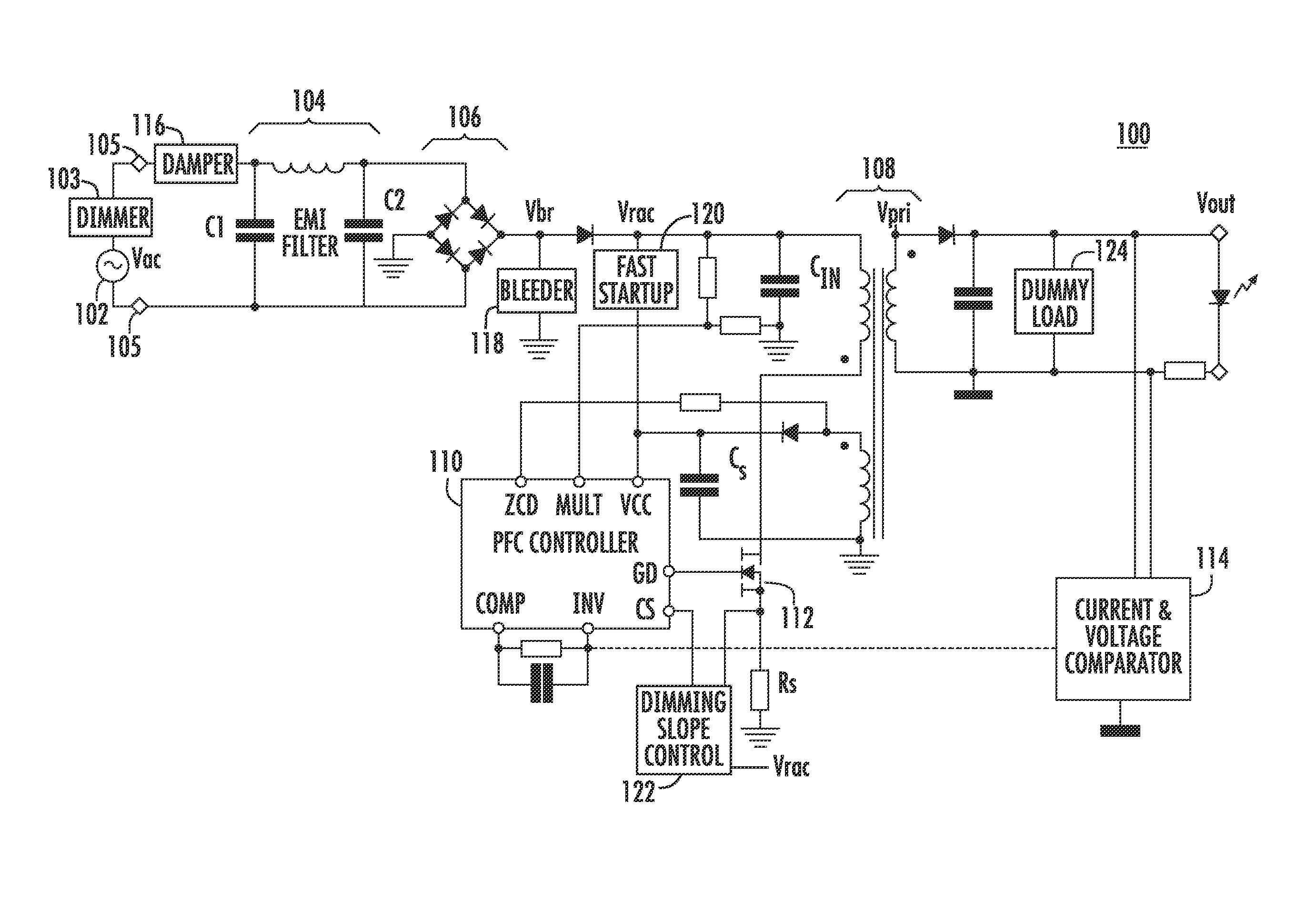
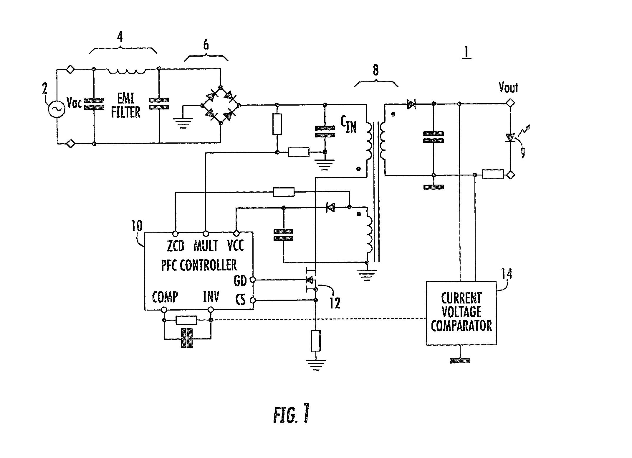
[0054]In accordance with preferred embodiments of the present invention, additional components are added to a PFC LED power supply to improve performance, in particular with regard to the problems of the conventional power supply discussed above. For example, as shown in FIG. 8, the dimmable PFC LED power supply 100 in accordance with an embodiment of the present invention includes, in one aspect, the same elements as shown in FIG. 1, plus additional components. In order to work with a triac dimmer 103, these additional components, namely a damper 116, a bleeder circuit 118, a fast startup circuit 120, a dimming slope control 122, and a dummy load 124, are added to PFC flyback power supply, as shown in FIG. 8.

[0055]The dimmable power supply 100 in accordance with aspects of the present invention can provide deeper dimming, reduced or no flickering, quick startup even at low dimming level, compatibility with leading / trailing edge dimmers, and similar dimming characteristics of an inc...


PUM


Abstract

A power-factor-corrected power supply adapted to supply power to one or more light emitting diodes (LEDs), comprises: a triac dimmer electrically connected between an alternating current source and a bridge rectifier; a damping circuit electrically connected between the alternating current source and the bridge rectifier; a bleeder circuit configured to conduct current between a supply terminal of the bridge rectifier and ground only when a triac in the triac dimmer is not conducting current; a fast startup circuit configured to conduct current between the supply terminal of the bridge rectifier and a voltage supply terminal of a power-factor-corrected controller when the triac dimmer is initially turned on until a supply voltage capacitor coupled to the voltage supply terminal of the power-factor-corrected controller has charged; a dimming slope control circuit configured to reduce a first voltage sensed at a current sensing terminal of the power-factor-corrected controller, such that a reduced amount of current is supplied to the one or more LEDs at a given firing angle, wherein the first voltage is representative of a current flowing through a primary winding of a flyback transformer; and a dummy load circuit provided in parallel with the one or more LEDs to draw a holding current for the triac only after the triac is turned on.

Description

CROSS-REFERENCE TO RELATED APPLICATION[0001]This application claims priority to U.S. Provisional Patent Application No. 61 / 332,485, filed May 7, 2010, which is hereby incorporated by reference.BACKGROUND OF THE INVENTION[0002]The present invention relates to apparatuses and methods for supplying power to LEDs.[0003]FIG. 1 shows a typical schematic of a conventional power-factor-corrected (PFC) flyback converter 1 for driving light emitting diodes (“LEDs”). The PFC driver circuit 1 has advantages of a low number of components, a high power factor, a constant average output current to the LEDs, and a small transformer size. In the PFC driver circuit 1, an input stage includes an AC power supply 2 coupled to an EMI filter stage comprised of an inductor and two capacitors. The input AC signal is then full wave rectified by the diode bridge rectifier 6, which produces a full wave rectified signal for input to the transformer stage 8. The output of the transformer stage 8 is output to the...

Claims


Application Information

Patent Timeline
Patent Type & Authority Patents(United States)
IPC IPC(8): H05B37/02H05B37/00H05B41/24H05B41/28H05B41/16H05B41/36H05B44/00
CPCY02B20/347H05B41/36Y02B20/348H05B33/0815H05B37/00H05B41/28H05B37/02Y02B20/30H05B45/385H05B45/3575H05B45/355
Inventor LEUNG, WA-HINGSIU, KAM WAH
Owner HUIZHOU LIGHT ENGINE LTD
Why Eureka
Try Eureka