Check patentability & draft patents in minutes with Patsnap Eureka AI!

Support structure and mounting componet for a thrust inverter

a technology of thrust reverser and support structure, which is applied in the direction of propulsive elements, air transportation, aircraft navigation control, etc., can solve the problems of large number of fastening members (screws, rivets), large amount of time involved in mounting/detaching these spacers on the front half frame and relevant beams, etc., to reduce manufacturing costs, reduce the number of component parts, and reduce the effect of mounting/detaching times

Active Publication Date: 2014-07-29
SAFRAN NACELLES
View PDF10 Cites 2 Cited by
  • Summary
  • Abstract
  • Description
  • Claims
  • Application Information

AI Technical Summary

Benefits of technology

This solution significantly reduces assembly time and manufacturing costs while minimizing the mass of the thrust reverser, enhancing efficiency and reducing the weight penalty associated with fastening elements.

Problems solved by technology

The operations of mounting / demounting these spacers on the front half-frame and on the relevant beam involve a large amount of time.
Moreover, the large number of fastening members (screws, rivets) employed represents a considerable mass, this obviously being undesirable in the aeronautical sector where it is known that each gram represents a penalty of about 1 US dollar on the price of the equipment in question.

Method used


Image

  • Support structure and mounting componet for a thrust inverter
  • Support structure and mounting componet for a thrust inverter

Examples


Embodiment Construction

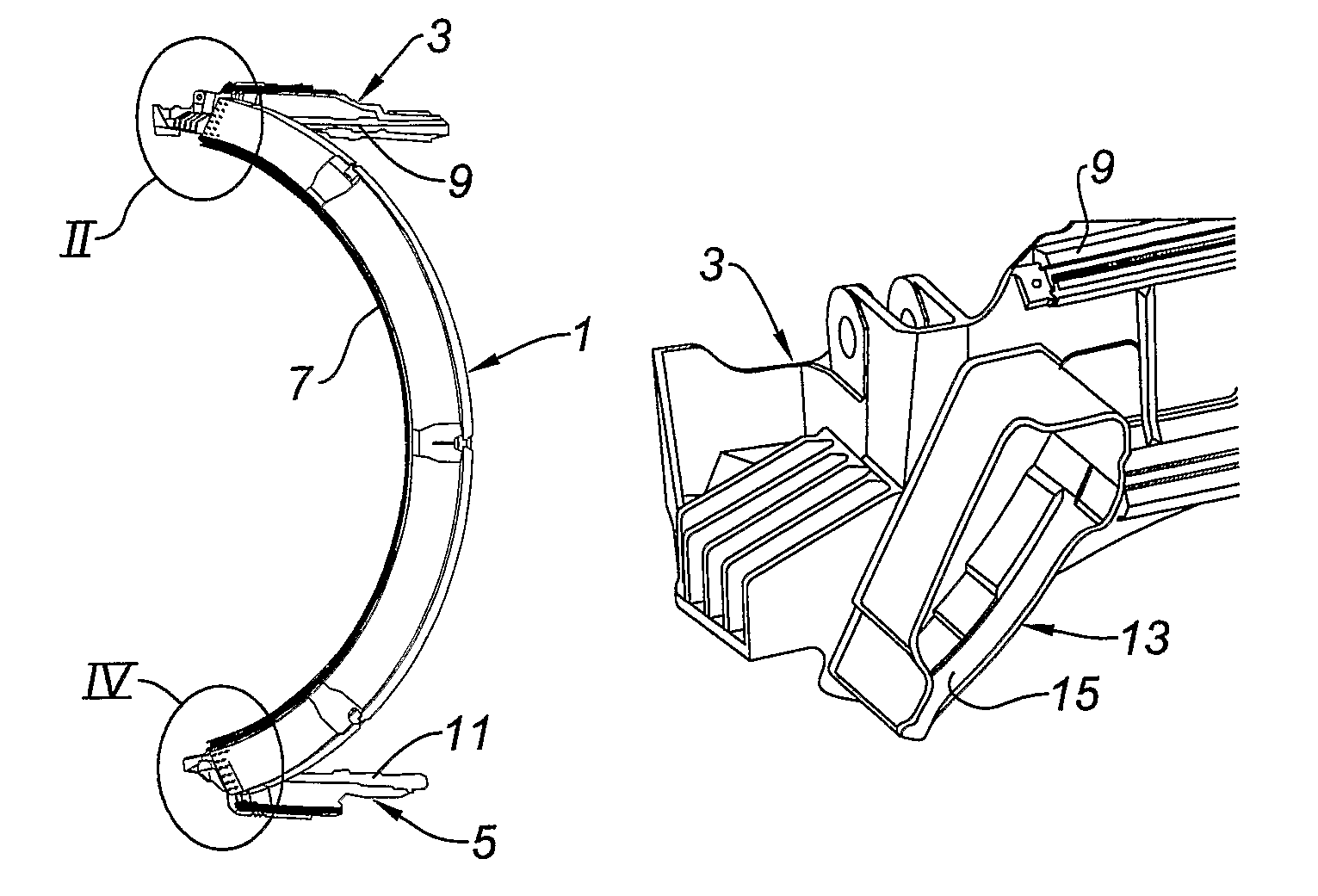
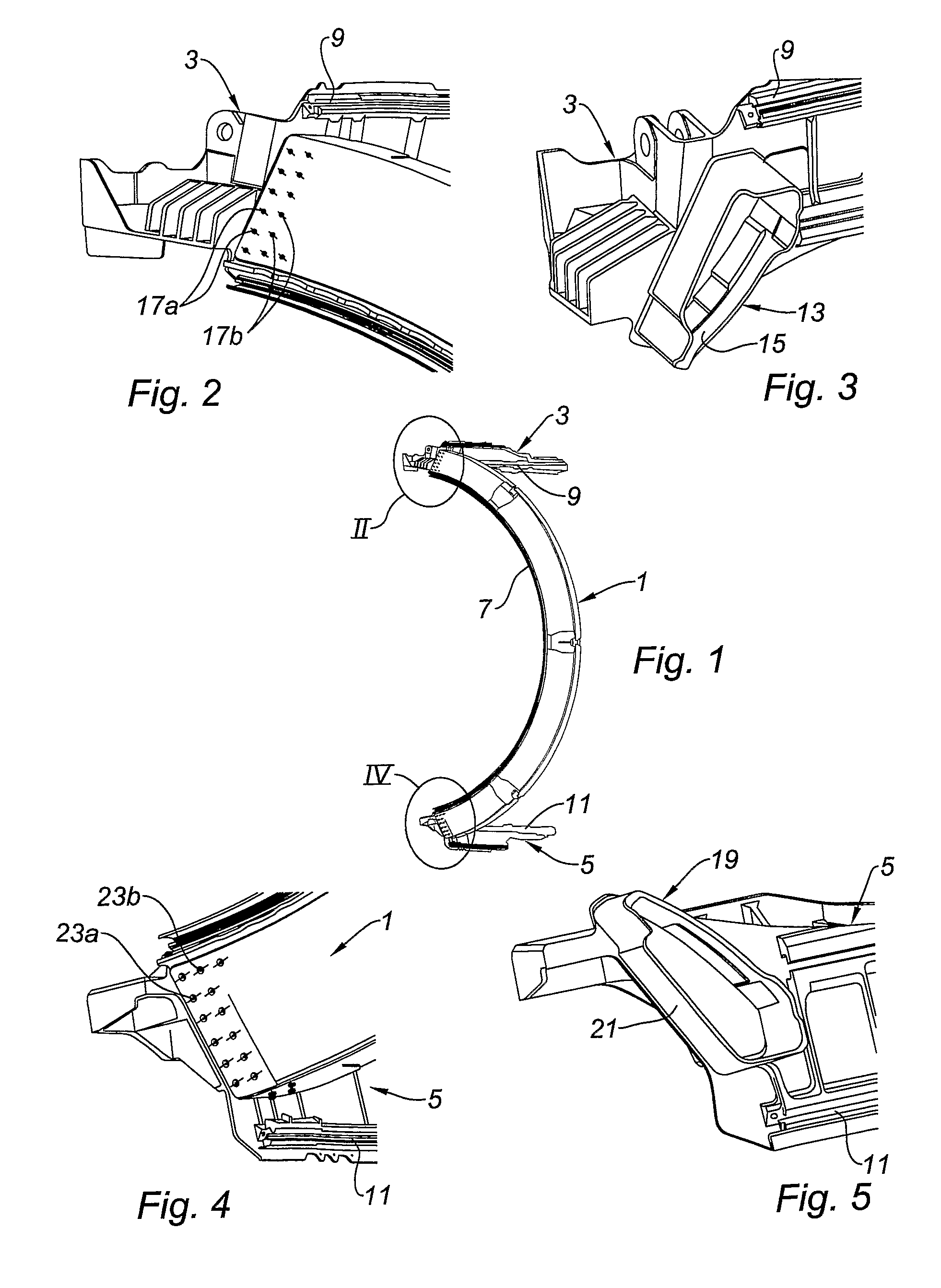
[0028]Referring now to FIG. 1, this illustrates a front half-frame 1 fastened to an upper beam 3 and a lower beam 5.

[0029]The terms “upper” and “lower” are understood in relation to the final positioning of the beams 3 and 5 in a thrust reverser.

[0030]The beams 3 and 5 are often denoted respectively by the terms “12 o'clock” and “6 o'clock” by analogy with the positioning of the hands on a clock dial.

[0031]The assembly formed by the front half-frame 1 and the two beams 3 and 5 constitutes the half-structure of a thrust reverser, which means that, in reality, a symmetrical half-structure completes that illustrated in FIG. 1, so as to form substantially a closed circle.

[0032]The two front frames of these two half-structures are intended, in particular, to make it possible to fasten the thrust reverser to the blower housing of the turbojet engine of an aircraft (not illustrated).

[0033]In particular, as is known per se, the inner edge 7 of the front half-frame 1 is intended to be insert...


PUM


Abstract

Disclosed is a structure for a grid-type thrust reverser, the reverser including an upper beam, a lower beam, and two half-frames fastened to the upper beam and the lower beam, and hollow structures defined by the two half-frames, the hollow structures each having upper ends and lower ends, wherein at least one of the upper and lower beams includes integral parts delimited by walls, the walls forming casings fitted into and blocking corresponding ends of the half-frames.

Description

TECHNICAL FIELD[0001]The present invention relates to a structure for a thrust reverser.BACKGROUND[0002]As is known per se, a thrust reverser, particularly of the grid type, comprises, in particular, a circular element making it possible to fasten this reverser to the blower housing.[0003]This circular element is usually called a front frame and is composed, in fact, of two front half-frames, the ends of each of these half-frames being connected respectively to an upper beam and to a lower beam.[0004]These beams, which form part of the structural elements of the thrust reverser, have the function, in particular, of receiving rails making it possible to effect the sliding of the thrust reverser between its “direct jet” and “reversed jet” positions.[0005]In the prior art, each front half-frame is connected to its upper and lower beams by means of spacers attached by fastening, on the one hand, to the relevant end of the front frame and, on the other hand, to the relevant beam.[0006]Th...

Claims


Application Information

Patent Timeline
Patent Type & Authority Patents(United States)
IPC IPC(8): F02K3/02B05B12/00F01D25/28F02K1/54F02K1/72B64D27/40
CPCF02K1/72F01D25/28Y02T50/671F05D2260/30Y02T50/60
Inventor ELEGOET, JEAN-YVES
Owner SAFRAN NACELLES
Features
  • R&D
  • Intellectual Property
  • Life Sciences
  • Materials
  • Tech Scout
  • Unparalleled Data Quality
  • Higher Quality Content
  • 60% Fewer Hallucinations
Learn More