Light emitting device in which traces of light emitting elements merge into a single trace and lighting apparatus including the same

a technology of light emitting elements and light emitting devices, which is applied in the direction of lighting and heating apparatus, discharge tube luminescnet screens, lighting support devices, etc., can solve the problem of not being able to obtain high-quality lighting, and achieve excellent lighting quality

Active Publication Date: 2014-08-12
NICHIA CORP
View PDF7 Cites 6 Cited by
  • Summary
  • Abstract
  • Description
  • Claims
  • Application Information

AI Technical Summary

Benefits of technology

[0007]Accordingly, an object of embodiments of the present invention is to provide a light emitting device and a lighting apparatus having excellent lighting quality with the use of a light-concentrating device for condensing light.
[0029]According to the present invention, there can be provided a light emitting device and a lighting apparatus having excellent lighting quality with using a light-concentrating device for condensing light.

Problems solved by technology

However, these conventional lighting apparatuses have a problem that when the concentration of light is performed by using a light-concentrating device such as a lens and a reflector, light having deviation in color (i.e., uneven color) is projected on the walls and floors, and thus, high quality lighting cannot be obtained.

Method used


Image

  • Light emitting device in which traces of light emitting elements merge into a single trace and lighting apparatus including the same
  • Light emitting device in which traces of light emitting elements merge into a single trace and lighting apparatus including the same
  • Light emitting device in which traces of light emitting elements merge into a single trace and lighting apparatus including the same

Examples


example 1

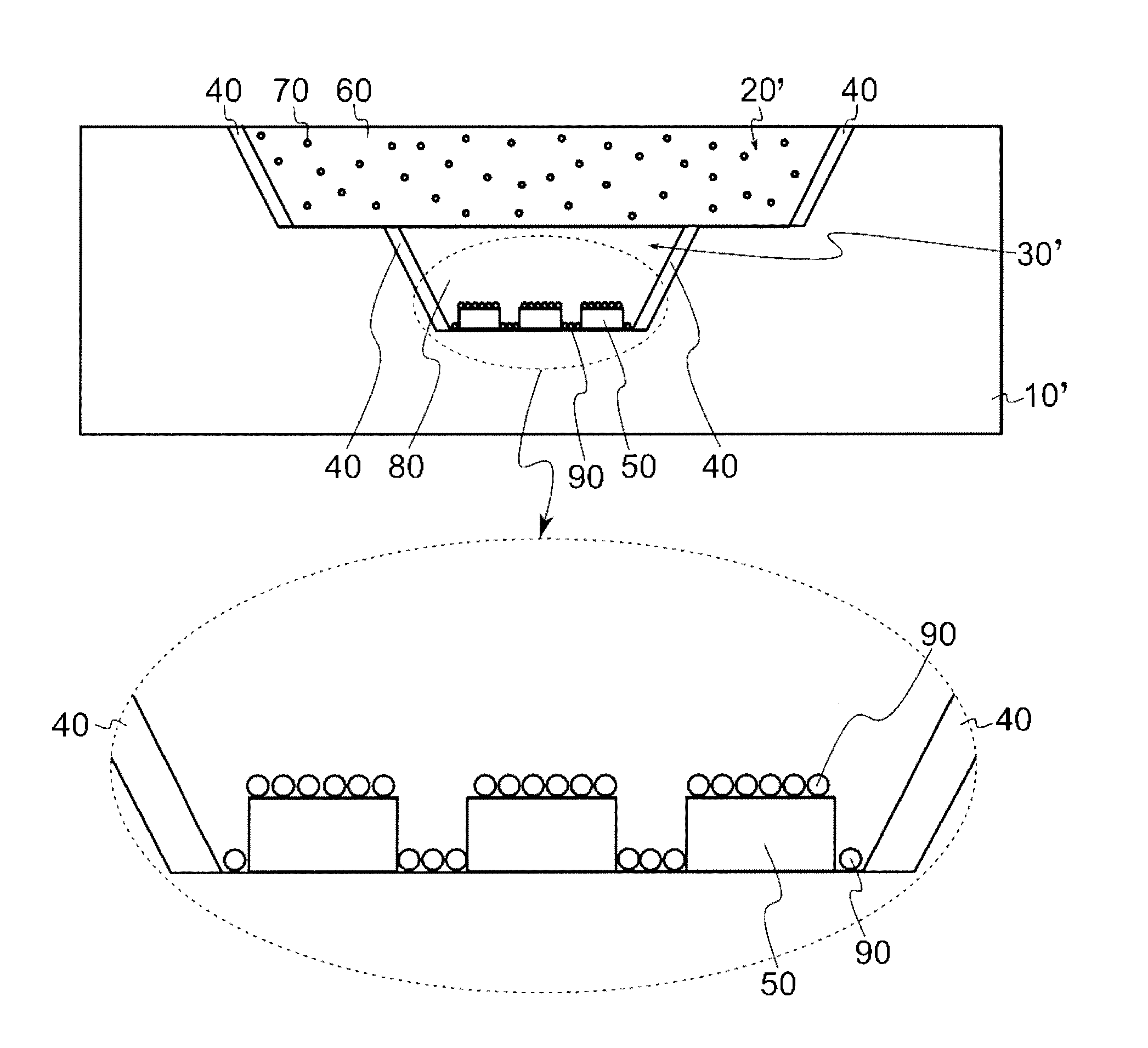
[0168]FIGS. 13(a) and 13(b) are diagrams each illustrating a light emitting device according to Example 1 of the present invention. FIG. 13(a) is a schematic plan view showing a light emitting device according to Example 1 of the present invention and FIG. 13(b) is a schematic cross sectional view taken along line A-A of FIG. 13(a).

[0169]As shown in FIGS. 13(a) and 13(b), a light emitting device according to Example 1 of the present invention includes a first recess 21′, a second recess 31′ formed in the bottom surface of the first recess 21′, a plurality of light emitting elements 51 arranged on the bottom surface of the second recess 31′, a first layer 61 containing light-diffusing material particles (not shown) and sealing the first recess 21′, and a second layer 81 containing fluorescent material particles (not shown) and sealing the second recess 31′, a lead frame 101, and a protective element 111.

[0170]In the case of the first layer 61, when the light-diffusing material partic...

example 2

[0179]FIGS. 14(a) to 14(e) are diagrams describing a light emitting device according to Example 2 of the present invention. FIG. 14(a) is a schematic perspective view seen from above, FIG. 14(b) is a schematic perspective view seen from below, FIG. 14(c) shows six schematic orthographic views, FIG. 14(d) is a schematic cross-sectional view taken along line A-A in FIG. 14(c), and FIG. 14(e) is a schematic plan view. Note that, in FIG. 14(e), the sealing member is omitted to show the light emitting elements.

[0180]As shown in FIG. 14, in the light emitting device according to Example 2 of the present invention, the lead frame 101a is disposed on the entire bottom surface of the second recess 31′. Accordingly, in the light emitting device according to Example 2 of the present invention, a uniform reflectance can be obtained at the bottom surface of the second recess 31′.

[0181]The plurality of light emitting elements 51 are connected to the lead frame 101a disposed at the entire bottom s...


PUM


Abstract

A light emitting device comprises a plurality of light emitting elements sealed with a fluorescent material containing member, each of the plurality of light emitting elements having an upper surface. The plurality of light emitting elements are arranged such that, in a planar view of a light emitting surface, when the plurality of light emitting elements are projected in a parallel direction in a plane of the light emitting surface, traces of the upper surfaces of the plurality of the light emitting elements merge into a single trace. A light emitting apparatus comprises a light-concentrating device, and the light emitting device.

Description

CROSS-REFERENCE TO RELATED APPLICATIONS[0001]This application claims priority to and the benefit of Japanese Patent Application No. 2011-239855, filed on Nov. 1, 2011; Japanese Patent Application No. 2011-261078, filed on Nov. 29, 2011; Japanese Patent Application No. 2011-268438, filed on Dec. 7, 2011; and Japanese Patent Application No. 2012-197987, filed on Sep. 8, 2012, each of which is hereby incorporated by reference in their entireties.BACKGROUND[0002]1. Technical Field[0003]The present disclosure relates to a light emitting device used for a lighting apparatus, etc.[0004]2. Discussion of Related Art[0005]There have been proposed lighting apparatuses in which a plurality of groups of light emitting devices with a circular shape or a polygonal shape are arranged concentrically (see, e.g., JP 2005-159262 A).[0006]However, these conventional lighting apparatuses have a problem that when the concentration of light is performed by using a light-concentrating device such as a lens ...

Claims


Application Information

Patent Timeline
Patent Type & Authority Patents(United States)
IPC IPC(8): F21Y105/00F21S8/04H01L25/075H01L33/50
CPCH01L25/0753H01L33/50F21Y2101/02H01L2924/0002F21Y2105/003F21S8/04H01L2924/00F21Y2105/12F21Y2115/10F21Y2105/10
Inventor MIYAIRI, HIROSHITOKUNAGA, EIJI
Owner NICHIA CORP
Why Eureka
Try Eureka