Flicker-free dimming circuit for non-point light source

a non-point light source, flicker-free technology, applied in the direction of electric variable regulation, process and machine control, instruments, etc., can solve the problems of not meeting the dimming requirement of the present panel lamp, the lack of constant power control mechanism, and the safety regulation. to achieve the effect of reducing the amplitude of rippl

Inactive Publication Date: 2017-12-26
EPISTAR CORP
View PDF3 Cites 1 Cited by
  • Summary
  • Abstract
  • Description
  • Claims
  • Application Information

AI Technical Summary

Benefits of technology

[0009]In addition, the converter has a sensing coil, a first core, a conversion chip, and a conversion switch, and the conversion coil is installed at a primary side of the first core, and the sensing coil is installed at a secondary side of the first core and electrically coupled to the conversion chip, and the conversion switch is electrically coupled to the conversion chip and the conversion coil, and when the conversion coil transmits the input voltage, the sensing coil senses a sensing voltage by the first core, and the sensing voltage is provided for the conversion chip to reference and then regulate the working period of the conversion switch to maintain the voltage value of the input voltage constant. The control coil module comprises a primary side coil, a second core, a secondary side coil and a regulation coil, and the primary side coil and the regulation coil are installed at a primary side of the second core, and the secondary side coil is installed at a secondary side of the second core, and the regulator is electrically coupled to the primary side coil and the regulation coil, and the primary side coil is electrically coupled to the conversion module for receiving the operating voltage, and the secondary side coil forms the driving voltage through the second core magnetic induction while the regulation coil forms a regulation signal through the second core magnetic induction, and the regulation signal is provided for the regulator to regulate the working period of the primary side coil. The regulator has a regulation chip, a regulation switch, and a detection element, and the detection element is electrically coupled to the regulation coil and the regulation chip, and the regulation switch is electrically coupled to the regulation chip and the primary side coil, and when a regulation voltage is obtained from the operating voltage of the magnetic induction of the regulation coil, the detection element detects and forms a regulation signal and feeds back the regulation signal to the regulation chip, so that the regulation chip regulates the working period of the regulation switch to regulate the cycle time of the operating voltage received by the primary side coil, so as to achieve a constant voltage effect.
[0010]In summation, the present invention bases on reverse thinking to apply a conventional two-stage isolated power conversion circuit in the LED lamp with a wide light source area and uses a primary side boost circuit to raise the voltage value of the input voltage to a constant and then uses a primary side regulation (PSR) Fly-back circuit provide a constant output of the driving voltage to reduce the amplitude of ripples effectively, achieve the flicker-free lighting effect, and comply with the expectation of the international industrial economic development.

Problems solved by technology

However, the driving circuit 1 is a non-isolated circuit with a very low effect on a precise constant current, and thus causing an issue on safety regulations and an issue on Electromagnetic Compatibility (EMC) and failing to meet the dimming requirement of the present panel lamps.
Although the self-excited driving circuit has a simple structure, it lacks of a constant power control mechanism.
The output power usually rises with the input voltage, and thus the lamp cannot maintain a stable brightness which causes a quick ageing of the lamp.

Method used


Image

  • Flicker-free dimming circuit for non-point light source
  • Flicker-free dimming circuit for non-point light source
  • Flicker-free dimming circuit for non-point light source

Examples


Embodiment Construction

[0016]The above and other objects, features and advantages of this disclosure will become apparent from the following detailed description taken with the accompanying drawings.

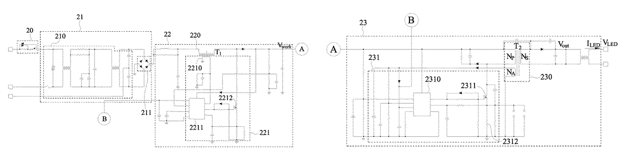
[0017]With reference to FIGS. 3 to 5 for a block diagram, a circuit diagram and a waveform chart of a preferred embodiment of the present invention respectively, the 15.7 W flicker-free dimming circuit for a non-point light source 2 adopt a two-stage isolated circuit structure to drive the operation of a lamp having a wide light source area and allow users to adjust the brightness of the lamp as needed while achieving the effects of providing a flicker free lighting effect and complying with the high-quality consumer requirements. The flicker-free dimming circuit for a non-point light source 2 comprises a TRIAC module 20, an input module 21, a conversion module 22 and an output module 23, and the input module 21 receives an AC voltage, and the TRIAC module 20 is electrically coupled to an external power supply...


PUM


Abstract

A flicker-free dimming circuit for non-point light source has a TRIAC module, an input module, a conversion module and an output module. The TRIAC module adjusts the voltage phase of an external power supply for the input module to export an input voltage, and the conversion module in a boost circuit structure is provided with a conversion coil and a converter to receive and raise the voltage value of the input voltage to a voltage value of an operating voltage and then supplies the operating voltage to the output module. The output module adopts a fly-back circuit structure and induces the operating voltage to form a driving voltage in a constant value and then outputs the driving voltage to a lamp with a relatively wide light source area. In this way, the panel lamp can meet high safety standards and enhance its product adaptability and competiveness.

Description

CROSS-REFERENCE TO RELATED APPLICATIONS[0001]This non-provisional application claims priority under 35 U.S.C. §119(a) on Patent Application No(s). 105140045 filed in Taiwan, R.O.C. on Dec. 5, 2016, the entire contents of which are hereby incorporated by reference.FIELD OF THE INVENTION[0002]The present invention generally relates to the field of power conversion device, particularly to a flicker-free dimming circuit for a non-point light source that supports a TRI-electrode AC switch (TRIAC).BACKGROUND OF THE INVENTION1. Description of the Related Art[0003]To create a comfortable, bright, and stylish space for reading or work, many people install simple and elegant panel lamps at indoor ceilings. Of course, a driving circuit for converting the mains power is required for driving the light source components of the panel lamps, supplying electric power required by the operation of the light source components and stabilizing the overall work quality of the lamps. With reference to FIG....

Claims


Application Information

Patent Timeline
Patent Type & Authority Patents(United States)
IPC IPC(8): H05B37/02H02M3/335H05B33/08H02M1/08H05B44/00H05B45/59
CPCH05B33/0818H05B33/0851H02M3/33523H02M1/081H05B33/0815H05B45/10H05B45/38H05B45/385H05B45/59H02M3/33507H02M5/257H02M1/007
Inventor WU, CHIH-HSIENCHUANG, KAI-CHENGHUNG, CHENG-HAN
Owner EPISTAR CORP
Why Eureka
Try Eureka