Light source mechanism for an imaging apparatus

a technology of light source mechanism and imaging apparatus, which is applied in the direction of lighting and heating apparatus, lighting device details, electric lighting, etc., can solve the problems of tube not being able unable to provide the light source, and unable to provide the required light source, etc., to achieve stable illumination, improve imaging quality, and low cost

Inactive Publication Date: 2010-10-26
INTELLECTUAL VENTURES I LLC
View PDF15 Cites 2 Cited by
  • Summary
  • Abstract
  • Description
  • Claims
  • Application Information

AI Technical Summary

Benefits of technology

[0012]Accordingly, it is a primary object of the present invention to provide a light source mechanism for an imaging mechanism, in which a point light source is applied to provide improved imaging quality and advantages of low cost, stable illumination, long life term and a wider application range.

Problems solved by technology

Yet, it is well known that the fluorescent tube can only provide lights limited to a narrow wave length range, and generally within the range of visible lights.
Under such an arrangement, it is obvious that the fluorescent tube cannot provide the required light source to perform the scanning.2. The conventional fluorescent tube is generally a product of short-life term and is vulnerable to be broken as well as invaded by gas.3. The illumination provided by the conventional fluorescent tube is sometimes unstable and consequently affects the scanning quality of the imaging apparatus.4. The unit price of the conventional fluorescent tube is usually high, so that the cost of the imaging apparatus cannot be reduced to a competitive level.

Method used


Image

  • Light source mechanism for an imaging apparatus
  • Light source mechanism for an imaging apparatus
  • Light source mechanism for an imaging apparatus

Examples


first embodiment

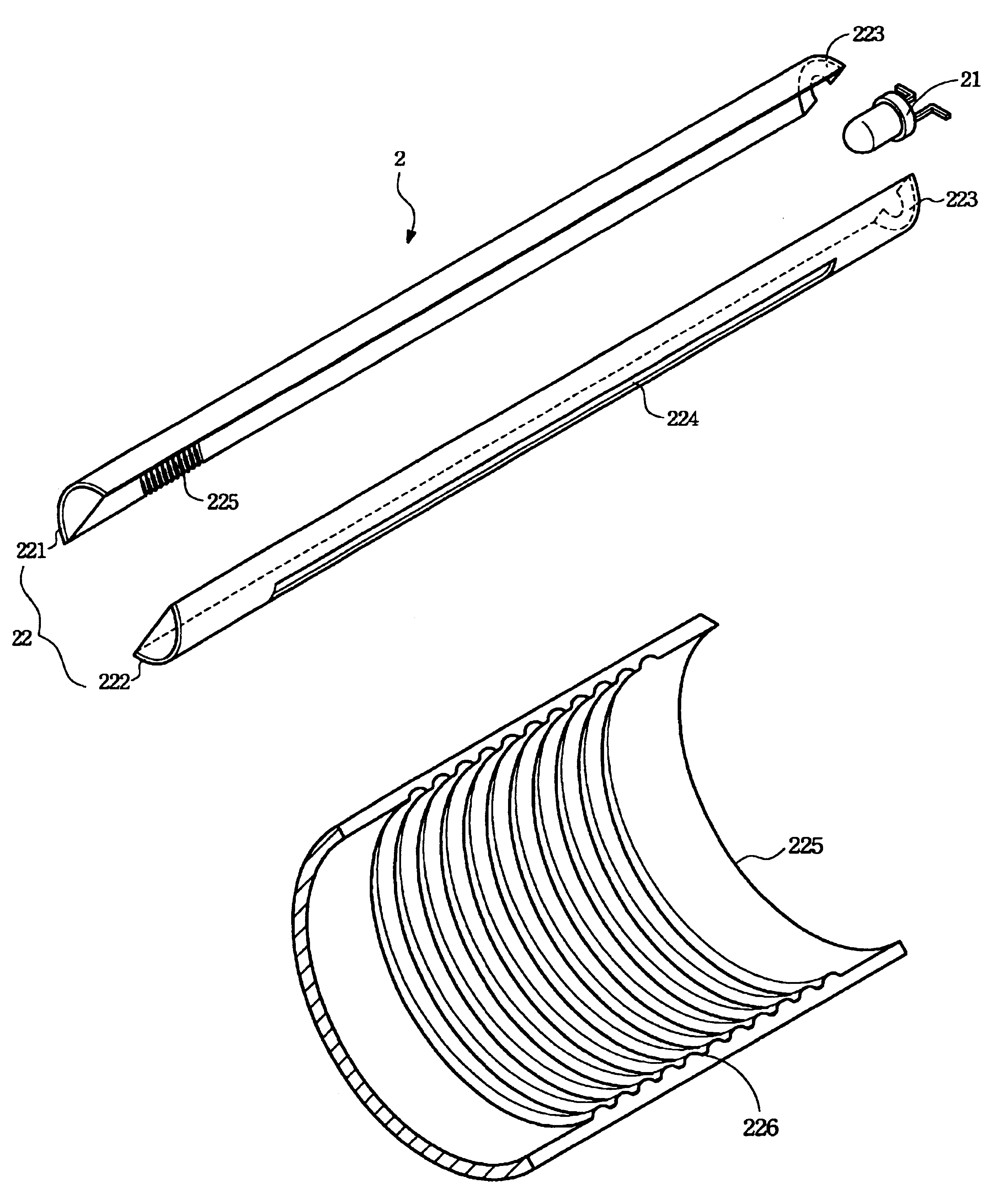
[0022]Referring now to FIG. 2, the light source mechanism for an imaging apparatus in accordance with the present invention is shown explodedly.

[0023]The light source mechanism 2 as shown includes a single point light source 21 and a light shield 22. The point light source 21 can be a light emitting diode (LED) which has advantages of low cost, longer life term, stable illumination and a wider wave range for application. To meet the requirement of the line light source for scanning the document, the light source mechanism 2 of the present invention utilizes the light shield 22 to transform the lights of the point light source 21 into an applicable line lights.

[0024]As shown in FIG. 2, the light shield 22 of the present invention, shaped as a long hollow pipe structure, includes an upper half 221 and a mating lower half 222. The light shield 22 can be preferably made of opaque materials. One end of the light shield 22 includes a mounting element 223 for installing the point light sou...

second embodiment

[0029]Referring now to FIG. 4, the light source mechanism for an imaging apparatus in accordance with the present invention is shown explodedly.

[0030]In the second embodiment, the light source mechanism 2a can include two point light source 21a and 21b, and a light shield 22a. The point light source 21a or 21b can be a light emitting diode (LED) which, as said in previous description, has advantages of low cost, longer life term, stable illumination and a wider wave range for application. These two point light sources 21a and 21b are preferably mounted to opposing ends of the light shield 22a.

[0031]As shown in FIG. 4, the light shield 22a of the present invention, shaped as a long hollow pipe structure, includes an upper half 221a and a mating lower half 222a. The light shield 22a can be preferably made of opaque materials. Each of both ends of the light shield 22a can include a respective mounting element 223a or 223b for installing the respective point light source 21a or 21b. One...


PUM


Abstract

A light source mechanism for an imaging apparatus comprises at least a point light source and a light shield. The point light source located at one end of the light shield is used for providing illumination to the imaging apparatus during a scanning process. The light shield is a hollow pipe structure and further includes a long slot lying along an axial longitudinal direction thereof for allowing lights to leave the light shield. An inner surface of the light shield is made as a diffusion surface for evenly diffusing lights inside the light shield, by which a homogeneous line light source for the scanning process is formed at the long slot of the light shield.

Description

BACKGROUND OF THE INVENTION[0001](1) Field of the Invention[0002]The invention relates to a light source mechanism for an imaging apparatus, and more particularly to a combination which integrate a point light source with a light shield for producing a line light source with enhanced homogeneous illumination.[0003](2) Description of the Prior Art[0004]An imaging apparatus or a scanner is one of popular computer peripherals. In an imaging apparatus, an internal light source is used to generate an image from a document rested upon a document plate. The image is then forwarded through a plurality of lenses and experiencing a proper travel path to reach a CCD for being transformed into digital signals. The digital signals are then sent to a computer for further image processing.[0005]Referring now to FIG. 1A and FIG. 1B, a perspective and a side views of a conventional light source mechanism are shown, respectively. The light source mechanism 1 mainly comprises a fluorescent tube 12 and...

Claims


Application Information

Patent Timeline
Patent Type & Authority Patents(United States)
IPC IPC(8): H04N1/04F21V5/00F21V3/00F21V11/00H04N1/46H04N1/028
CPCH04N1/0284H04N1/02815H04N1/02885
Inventor FANG, PO-HUA
Owner INTELLECTUAL VENTURES I LLC
Why Eureka
Try Eureka