Media processing device, check processing device, and method of controlling a media processing device

a media processing and check processing technology, applied in the direction of conveying record carriers, instruments, sensing by electromagnetic radiation, etc., can solve the problems of difficult reducing device size and long conveying path to the processing position, and achieve the effect of compact construction

Active Publication Date: 2015-02-17
SEIKO EPSON CORP
View PDF27 Cites 2 Cited by
  • Summary
  • Abstract
  • Description
  • Claims
  • Application Information

AI Technical Summary

Benefits of technology

[0026]The invention enables performing a second process determined according to the result of a first process from the normal process position irrespective of the length of the conveyance path and the locations of the process units. The media processing device and check processing device can therefore be built more compactly because limitations related to the conveyance path length and the relative positions of process units can be alleviated.

Problems solved by technology

When the next process applied to the medium changes according to the result of recording in the media processing device that conveys checks or other media and records images on the media while being conveyed, the conveyance path to the processing position must be sufficiently long, and reducing device size is difficult.

Method used


Image

  • Media processing device, check processing device, and method of controlling a media processing device
  • Media processing device, check processing device, and method of controlling a media processing device
  • Media processing device, check processing device, and method of controlling a media processing device

Examples


first embodiment

of a Reading Process

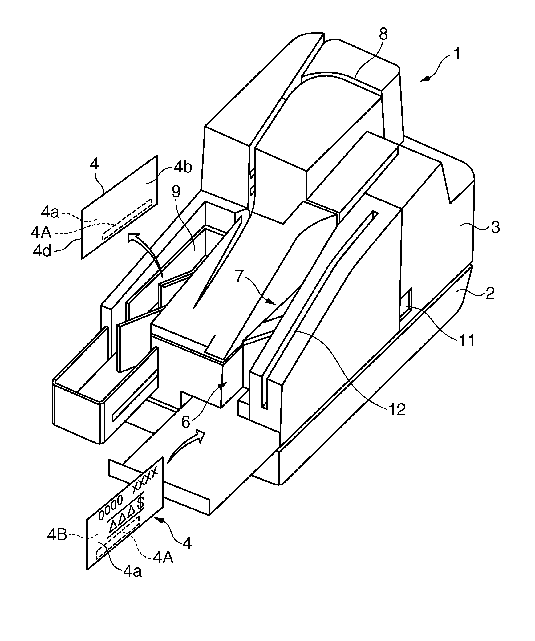
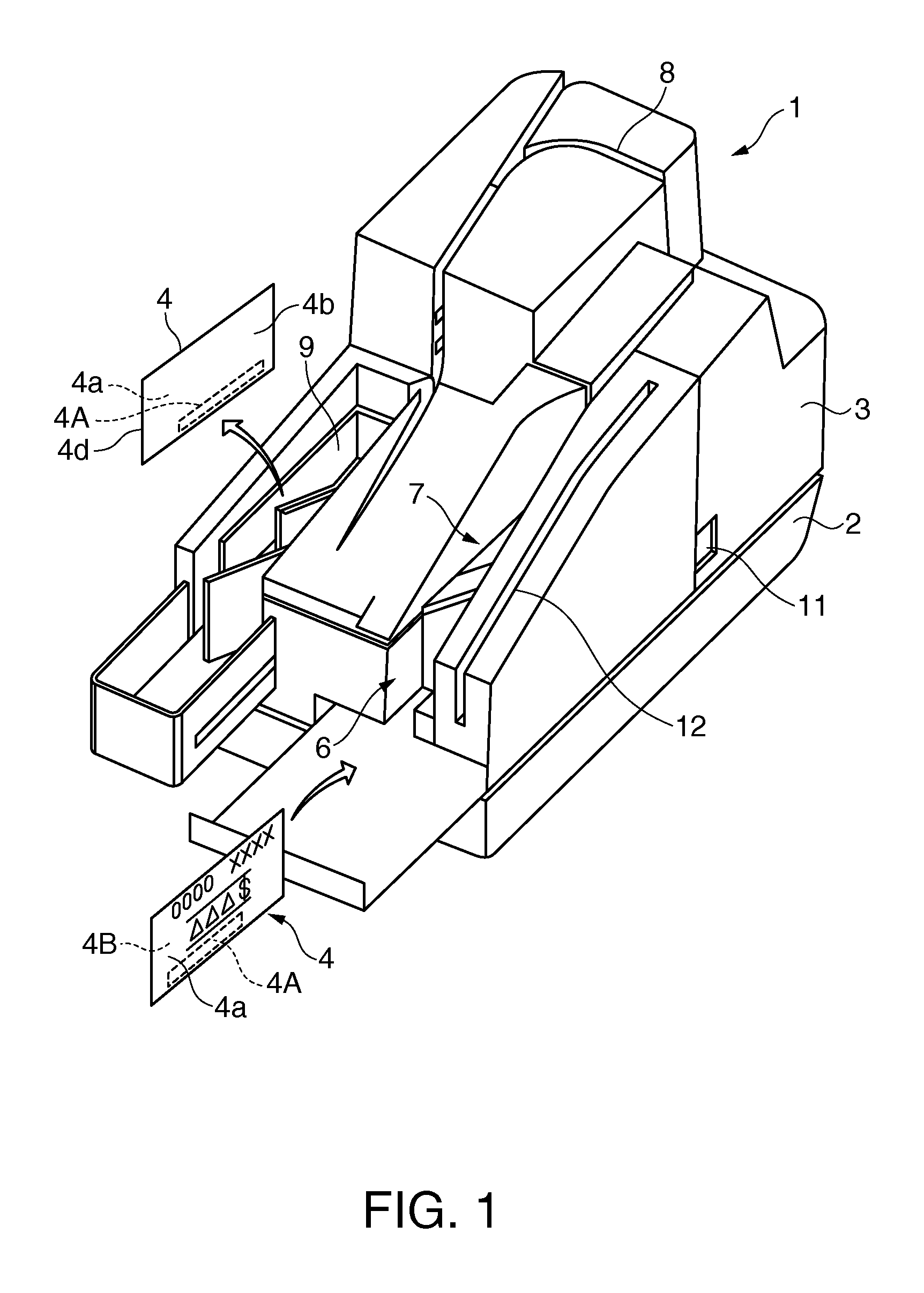
[0101]FIG. 7A and FIG. 7B schematically describe conveyance of a check 4, FIG. 7A showing when optically reading a check 4 is completed, and FIG. 7B showing the change in conveyance until the check 4 is discharged.

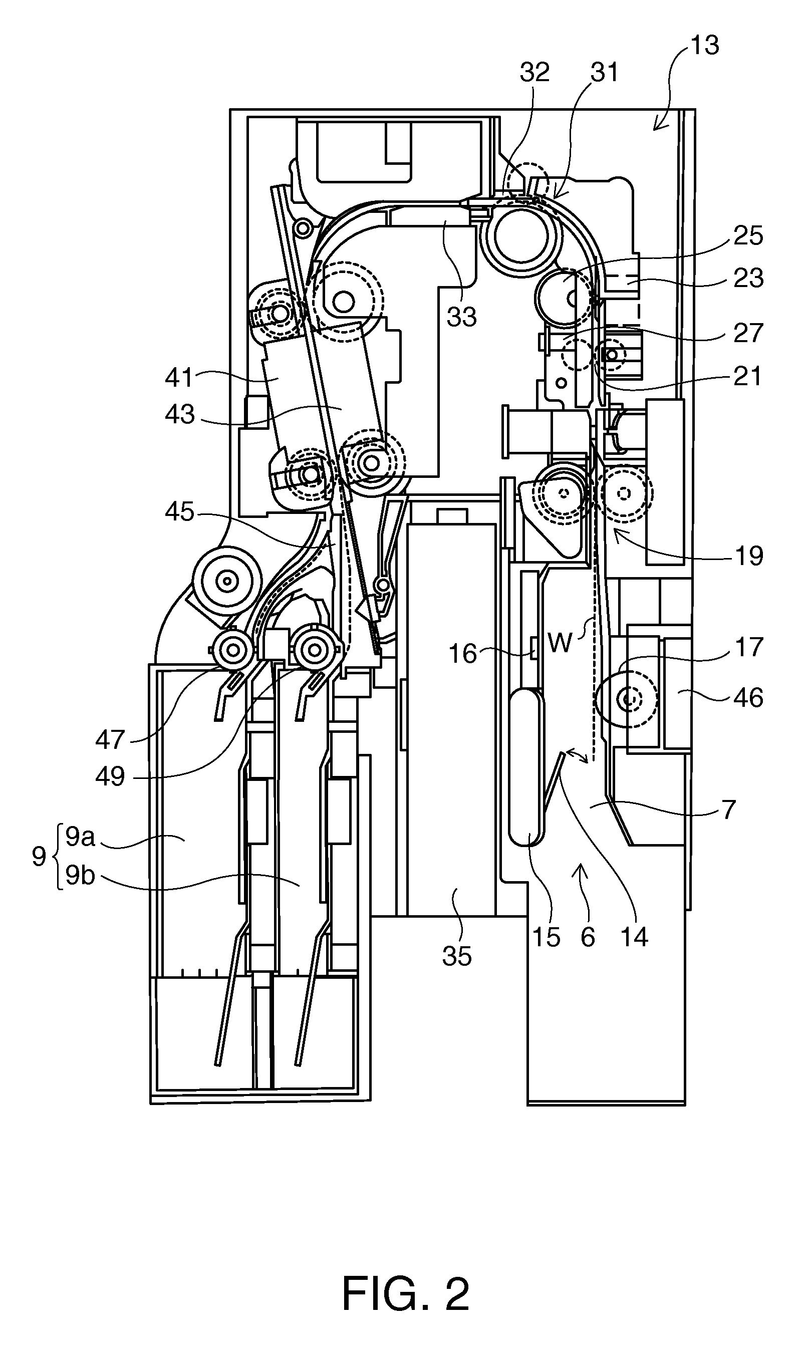
[0102]The horizontal axis shows the position on the conveyance path W in FIG. 7A and FIG. 7B. Positions (1) to (5) in the figures indicate specific process positions along the conveyance path W. More specifically, position (1) is the position where the ASF paper detector 16 detects a check 4; position (2) is the reading position where the MICR head 23 reads magnetically; position (3) is the recording position where the recording head 33 ejects ink and records; position (4) is the scanning position where the front CIS unit 41 and back CIS unit 43 read optically; and position (5) is the switching position of the diversion gate 45.

[0103]A check 4 is first detected by the ASF paper detector 16, and then fed into the conveyance path W by the pickup roller 17...

second embodiment

of a Reading Process

[0132]FIG. 9 is a flow chart of the operation of a media processing system 10 related to a second embodiment of a reading process according to the invention. In this second embodiment of a reading process, parts that are the same as in the media processing system 10 according to the first embodiment of a reading process described above are identified by like reference numerals, and further description thereof is omitted.

[0133]The operation shown in FIG. 9 is executed instead of the operation shown in FIG. 8. Note that steps performing the same operation as in FIG. 8 are identified by the same step numbers in FIG. 9.

[0134]The control unit 50 first executes steps S111 to S119 as described in the above first embodiment. After recording with the recording head 33 in step S119, the scanning control unit 50F starts scanning with the front CIS unit 41 and back CIS unit 43 (step S127), and starts sending the scanned image data through the interface unit 59 to the host co...


PUM


Abstract

A compact media processing device enables recording on a process medium and then processing the process medium based on the result of recording. The media processing device conveys a process medium and processes the conveyed process medium by a first process unit disposed to the conveyance path, and an operation selection unit then determines the content of the next operation based on the result of the first process. After the next operation is determined, the conveyance control unit conveys the process medium upstream to or upstream of the process position of a second process unit. A process control unit then applies the selected operation to the process medium by the second process unit that is disposed downstream from the first process unit on the conveyance path of the process medium.

Description

[0001]Priority is claimed under 35 U.S.C. §119 to Japanese Application nos. 2011-158663 filed on Jul. 20, 2011 and 2011-216111 filed on Sep. 30, 2011, which are hereby incorporated by reference in their entirety.BACKGROUND[0002]1. Technical Field[0003]The present invention relates to a media processing device, a check processing device, and a method of controlling a media processing device.[0004]2. Related Art[0005]Devices that read information from a slip or other document to be read, and change the discharge destination of the document according to the result of reading the document, are known from the literature. See, for example, Japanese Unexamined Patent Appl. Pub. JP-A-H09-62798. The device described in JP-A-H09-62798 reads a barcode from a sheet medium, which is the document to be read, and determines that sheets that are read successfully are normal sheets, and sheets for which reading failed are defective sheets. A control gate is then operated to change the output destina...

Claims


Application Information

Patent Timeline
Patent Type & Authority Patents(United States)
IPC IPC(8): G07F7/02G07F7/10G06K13/16G06Q20/04G07D7/04G07D11/00H04N1/00H04N1/203
CPCG07D11/0051G06Q20/042G06K13/16G07D7/04H04N1/00339H04N1/00689H04N1/00694H04N1/00705H04N1/00713H04N1/00734H04N1/00745H04N1/0075H04N1/00774H04N1/2034H04N2201/0081G07D7/004G07D11/20B65H7/12G06K7/10G06K13/12G07D13/00
Inventor TOSHIMA, KAZUYA
Owner SEIKO EPSON CORP
Why Eureka
Try Eureka