
Vibration isolating device for an elastic coupling of two components

a technology of vibration isolating device and elastic coupling, which is applied in the direction of spring/damper functional characteristics, machine supports, shock absorbers, etc., can solve the problems of comparatively low wear, and achieve the effects of simple design, light weight and inexpensiv

Active Publication Date: 2018-10-30
AIRBUS HELICOPTERS DEUT GMBH
View PDF14 Cites 2 Cited by
  • Summary
  • Abstract
  • Description
  • Claims
  • Application Information

AI Technical Summary

Benefits of technology

[0015]It is, therefore, an object of the present invention to provide a new vibration isolating device that is adapted for an elastic coupling of a first component to a second component and for vibration isolation in predetermined frequency ranges between said first and second components, said vibration isolating device being comparatively light-weight and inexpensive and having a simple design and an increased life time compared to conventional vibration isolating devices.
[0017]Advantageously, the vibration isolating device according to the present invention has a comparatively simple design with a reduced amount of bearings and is comparatively low-cost, as e.g. no expensive components, such as hydraulics and so on, are required for its implementation. In particular, instead of mechanical bearings elastic parts can be used, thus, leading to comparatively low wear. Furthermore, it is less demanding on manufacturing tolerances than comparative conventional vibration isolating devices, while providing a higher overall life time and allowing for reduced maintenance efforts. Moreover, the vibration isolating device according to the present invention provides for comparatively high fatigue strength, if the first and second elastically deformable plates are embodied by means of properly applied composite materials, in particular carbon composites. Finally, it can be built more compact and slender than conventional vibration isolating devices and, consequently, be used to replace e.g. existing connection struts in existing vibration isolating arrangements without need for any additional devices.
[0021]According to one aspect of the present invention, levers can be attached to the elastic plates in order to further amplify the lateral displacements Δbi at locations i on the levers. Usually, a maximum lateral displacement Δbi occurs at respective free ends of the levers, thereby increasing the ratio xi. Realistic values for xi in such a configuration with two elastic plates and corresponding levers are comprised in an interval from 2 to 50. The lateral displacements Δbi can even further be amplified by placing a third elastic plate between two locations i on the two other elastic plates, preferably instead of the corresponding levers.
[0022]Preferably, an underlying isolation frequency of the vibration isolating device according to the present invention is tuned with the corresponding vibration isolation masses Mi, the ratios xi and the stiffness of the applied elastic plates and the stiffness of springs Ki that can be arranged between locations i on the elastic plates. More specifically, increasing the stiffness of the elastic plates and / or the springs leads to a higher isolation frequency, while increasing the corresponding vibration isolation masses Mi or increasing the ratios xi at the corresponding vibration isolation masses Mi leads to a lower isolation frequency.

Problems solved by technology

In particular, instead of mechanical bearings elastic parts can be used, thus, leading to comparatively low wear.

Method used


Image

  • Vibration isolating device for an elastic coupling of two components
  • Vibration isolating device for an elastic coupling of two components
  • Vibration isolating device for an elastic coupling of two components

Examples


Embodiment Construction

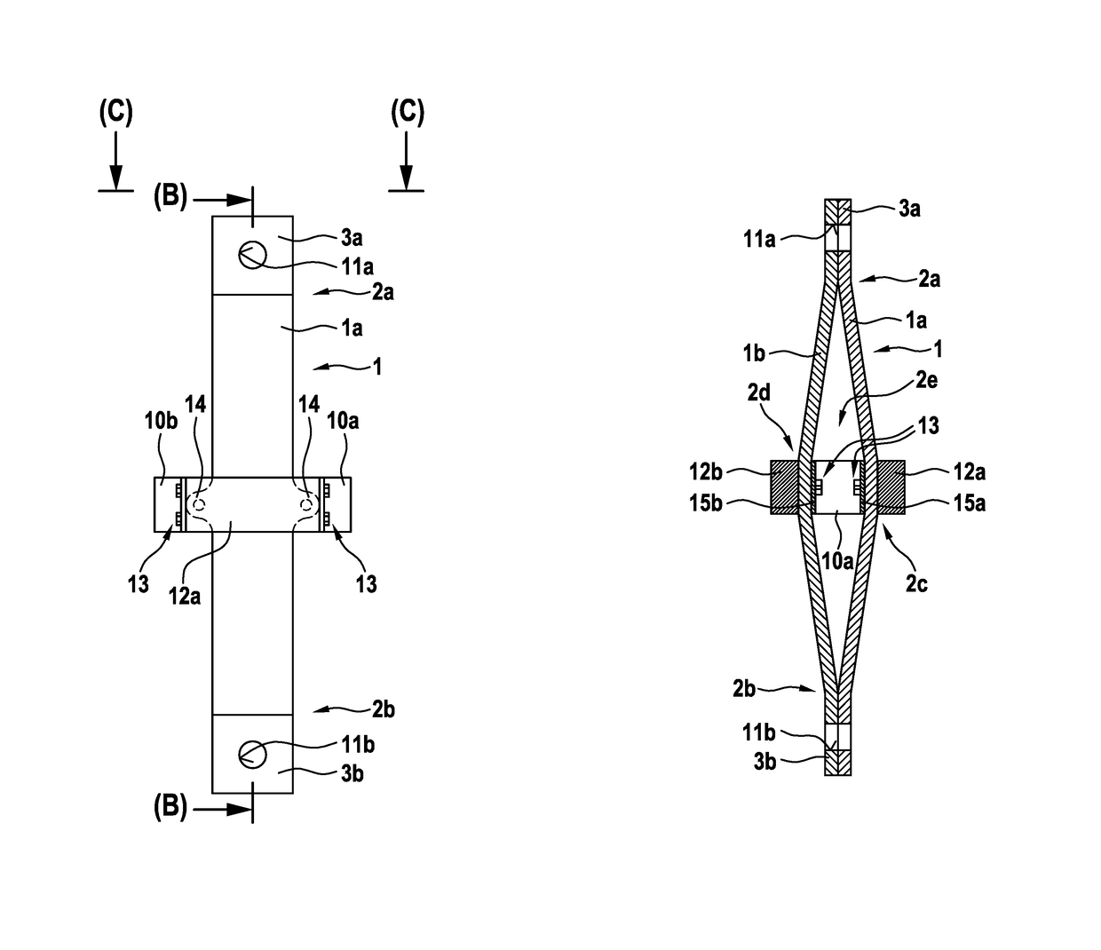
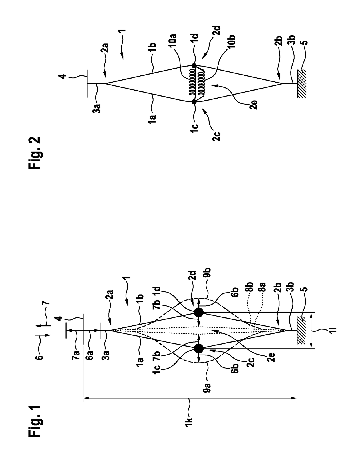
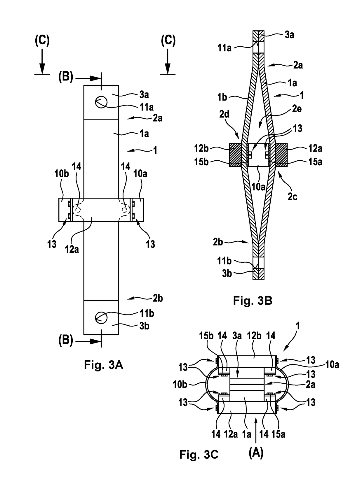
[0061]FIG. 1 shows a vibration isolating device 1 according to the present invention in unloaded state, which is preferably adapted for an elastic coupling of a first component 4 to a second component 5 and for vibration isolation in predetermined frequency ranges between these first and second components 4, 5. By way of example, the first component 4 can be a main gearbox (27a in FIG. 18) of a helicopter (27 in FIG. 18) and the second component 5 can be a fuselage (27b in FIG. 18) of this helicopter (27 in FIG. 18). However, it should be noted that the vibration isolating device 1 is not limited to use in helicopters, but can instead be used in any rotary wing aircraft and in aerospace engineering in general, as well as in other technical domains, such as automotive engineering or machinery, where vibration isolation is required.

[0062]According to one aspect of the present invention, the vibration isolating device 1 comprises at least a first and a second elastically deformable pla...


PUM

PropertyMeasurementUnit
frequencyaaaaaaaaaa
tension forceaaaaaaaaaa
compression forceaaaaaaaaaa

Abstract

A vibration isolating device that is adapted for an elastic coupling of a first component to a second component and for vibration isolation in predetermined frequency ranges between the first and second components, the vibration isolating device comprising at least a first and a second elastically deformable plate that are attached to each other in at least two separate connecting points, the first elastically deformable plate comprising a first curvature and the second elastically deformable plate comprising a second curvature, wherein the first and second curvatures are respectively located in a region between the at least two separate connecting points and arranged such that a gap is defined between the first and second elastically deformable plates.

Description

CROSS REFERENCE TO RELATED APPLICATION[0001]This application claims priority to European patent application No. EP 15400027.7 filed on Jun. 29, 2015, the disclosure of which is incorporated in its entirety by reference herein.BACKGROUND OF THE INVENTION(1) Field of the Invention[0002]The invention is related to a vibration isolating device that is adapted for an elastic coupling of a first component to a second component and for vibration isolation in predetermined frequency ranges between said first and second components, said vibration isolating device comprising the features of claim 1. The invention is further related to a helicopter with a first component that is elastically coupled to a second component by means of such a vibration isolating device, said helicopter comprising the features of claim 17.(2) Description of Related Art[0003]Vibration isolating devices that are adapted for an elastic coupling of two components and for vibration isolation in predetermined frequency r...

Claims


Application Information

Patent Timeline
Patent Type & Authority Patents(United States)
IPC IPC(8): F16M1/00F16F13/00F16F7/116F16F7/108B64C27/00F16F7/104F16F15/06F16F15/02F16F15/04
CPCF16F15/022B64C27/001F16F7/104F16F7/108F16F7/116F16F13/00F16F15/06F16F15/04F16F2228/066B64C2027/002F16F2224/02F16F2224/0208F16F2224/0241
Inventor BUESING, MORITZ
Owner AIRBUS HELICOPTERS DEUT GMBH
Learn More