Control of an electric machine

a technology of electric machines and electric motors, applied in the direction of electronic commutators, dynamo-electric machines, synchronous motor starters, etc., can solve the problems of becoming increasingly difficult to drive power into electric machines, and achieve the effect of increasing the advance tim

Active Publication Date: 2013-07-16
DYSON TECH LTD
View PDF85 Cites 3 Cited by
  • Summary
  • Abstract
  • Description
  • Claims
  • Application Information

AI Technical Summary

Benefits of technology

[0006]By exciting the winding in advance of back emf by a fixed period of time, the winding is excited in advance by an angle that varies with rotor speed. In particular, the advance angle increases proportionally with the speed of the rotor. Consequently, as the electric machine accelerates, current is driven into the winding at an increasingly early stage. As a result, more power is driven into the winding. Moreover, by employing a fixed advance time, there is no need to carry out on-the-fly calculations of what advance angle should be used for a particular rotor speed. Accordingly, the use of a fixed advance time presents an elegant method of ensuring that increasing power is driven into the electric machine as it accelerates.
[0010]The method preferably comprises sequentially exciting and freewheeling the winding. The winding is then excited in advance of the zero-crossings by the fixed advance time, and the winding is freewheeled over a freewheel time. In the region of falling back emf, less torque is achieved for a given level of current. Accordingly, by freewheeling the winding within this region, a more efficient electric machine may be realised. Additionally, as the back emf in the winding falls, current spikes may arise should the excitation voltage exceed the falling back emf. By freewheeling the winding within the region of falling back emf, current spikes may be avoided and thus a smoother current waveform may be achieved.
[0020]The control system may comprise a current controller for limiting current in the winding during excitation. This then prevents excessive currents building up in the winding, which might otherwise damage components of the control system or demagnetise magnets of the electric machine.
[0022]In a fourth aspect, the present invention provides a battery-powered product comprising an electric machine and a control system as described in any one of the preceding paragraphs. The control system then excites the winding with the voltage of the battery. The control system may then employ a fixed advance time that depends on the voltage level of the battery pack. In particular, the control system may increase the advance time as the battery pack discharges.

Problems solved by technology

It therefore becomes increasingly difficult to drive power into the electric machine.

Method used


Image

  • Control of an electric machine
  • Control of an electric machine
  • Control of an electric machine

Examples


Embodiment Construction

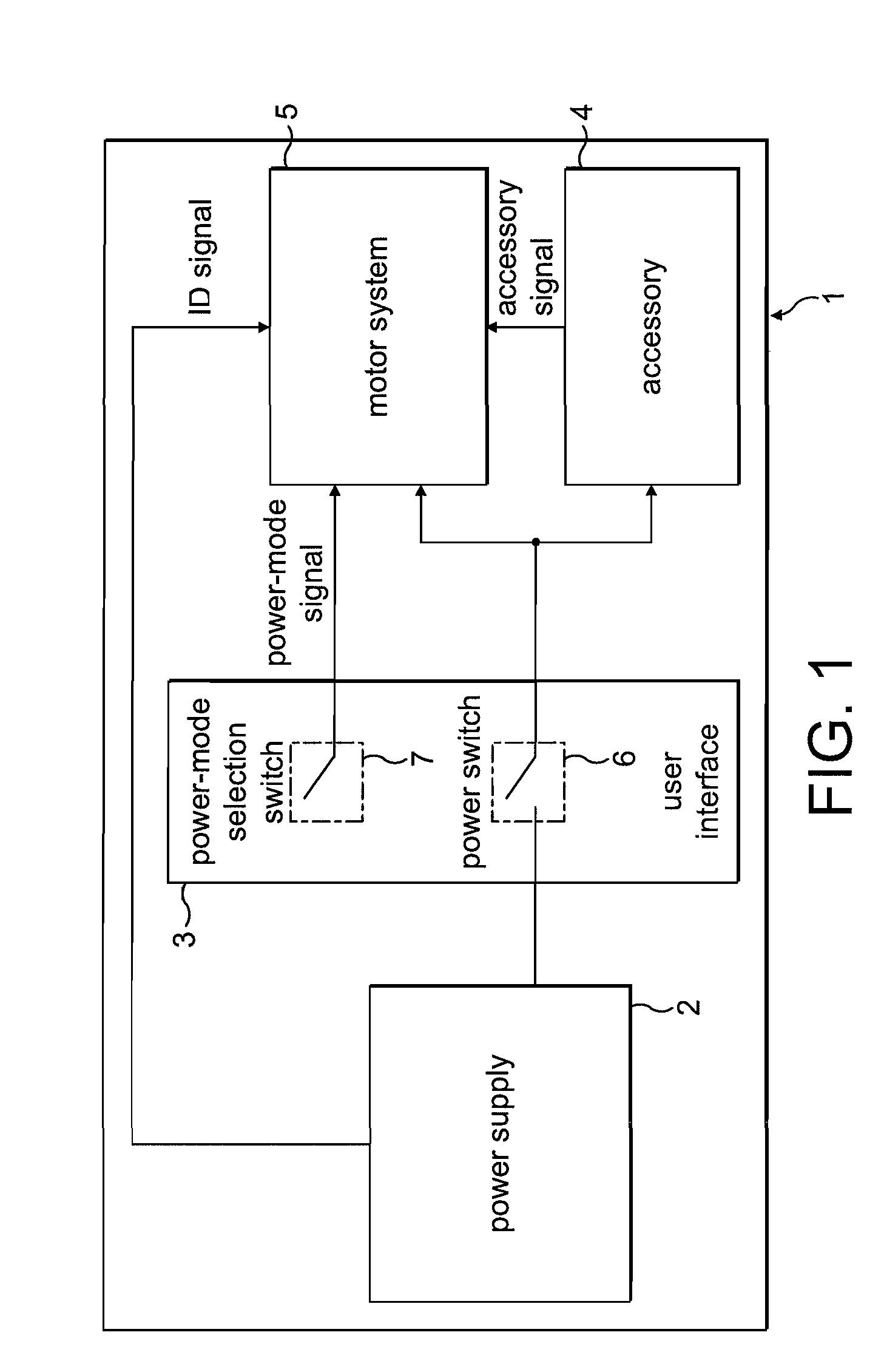
[0034]The product 1 of FIG. 1 comprises a power supply 2, a user interface 3, an accessory 4, and a motor system 5.

[0035]The power supply 2 comprises a battery pack that supplies a DC voltage to both the accessory 4 and the motor system 5. The power supply 2 is removable from the product 1 such that the product 1 may be used with different battery packs. For the purposes of the present description, the power supply 2 is either a 4-cell battery pack providing a 16.4 V DC supply or 6-cell battery pack providing a 24.6 V DC supply. In addition to providing a supply voltage, the power supply outputs an identification signal that is unique to the type of battery pack. The ID signal takes the form of a square-wave signal having a frequency that varies according to the type of battery pack. In the present example, the 4-cell battery pack outputs an ID signal having a frequency of 25 Hz (20 ms pulse length), while the 6-cell battery pack outputs an ID signal having a frequency of 50 Hz (10 ...


PUM


Abstract

A method of controlling an electric machine that includes exciting a winding of the electric machine in advance of zero-crossings of back emf by a fixed advance time over a range of speeds. Additionally, a control system for an electric machine, and a product incorporating the control system and electric machine.

Description

REFERENCE TO RELATED APPLICATIONS[0001]This application claims the priority of United Kingdom Application No. 0905883.5, filed Apr. 4, 2009, the entire contents of which are incorporated herein by reference.FIELD OF THE INVENTION[0002]The present invention relates to control of an electric machine.BACKGROUND OF THE INVENTION[0003]As the permanent-magnet rotor of an electric machine rotates, it induces a back emf in a winding of the electric machine. As the rotor accelerates, the magnitude of the back emf increases. It therefore becomes increasingly difficult to drive power into the electric machine. In order to overcome this difficulty, the winding may be excited in advance of the back end.[0004]Since the back emf increases with the speed of the rotor, the advance angle at which excitation leads the back emf ideally increases with the rotor speed. However, this then requires on-the-fly calculations in order to calculate the required advance angle for the speed of the rotor, and then...

Claims


Application Information

Patent Timeline
Patent Type & Authority Patents(United States)
IPC IPC(8): H02P6/18H02P1/04
CPCA47L5/24A47L9/0411A47L9/2831A47L9/2847H02P29/026A47L9/2889H02P6/008H02P6/085H02P6/145A47L9/2884H02P6/153H02P6/26H02P6/14
Inventor DAWE, ROGER MICHAELCLOTHIER, ANDREW CHARLTON
Owner DYSON TECH LTD
Why Eureka
Try Eureka