On-demand hydraulic pump for a transmission and method of operation

a hydraulic pump and hydraulic transmission technology, applied in the direction of piston pumps, positive displacement liquid engines, fluid couplings, etc., can solve the problems of fuel economy penalty during the remainder of the duty cycle of the vehicle, operation of the transmission at idle speed of the engine, etc., to achieve less torque, less horsepower, and better fuel economy in the vehicle

Active Publication Date: 2011-10-25
GM GLOBAL TECH OPERATIONS LLC
View PDF5 Cites 21 Cited by
  • Summary
  • Abstract
  • Description
  • Claims
  • Application Information

AI Technical Summary

Benefits of technology

[0004]To address the challenges of providing a sufficient hydraulic system for a transmission, a fixed displacement binary pump (i.e., a pump which can deliver full or partial volumetric output on demand) is provided for a powertrain on either a front wheel-drive or a rear wheel-drive vehicle (i.e., a vehicle wherein the engine powers the rear wheels through the transmission). A hydraulic system is operatively connected with first and second discharge ports of the pump and is operable to alternately permit fluid flow through both discharge ports (i.e., full displacement or volumetric output of the pump) or permit flow through only the first discharge port (i.e., partial displacement or volumetric output of the pump). A smaller pump displacement (as when the binary pump is operated at partial output) would require less torque and less horsepower to operate the pump, which leads to better fuel economy in the vehicle during steady-state operation. A binary fixed displacement pump can offer the faster response required to enable control of the transitions between partial output during steady-state operation of the transmission and the full output required during transient events such as transmission shifts. This response would be faster than a variable displacement vane pump (VDVP) for example, since it does not require the delay associated with moving a slide as in a VDVP. A further advantage over a VDVP may be improved volumetric efficiency due to reduced internal leakage, enabled by the absence of the moving slide.
[0006]To alleviate packaging limitations, especially in an off-axis rear wheel-drive embodiment, but not limited to such, the fixed displacement hydraulic pump may be configured to be housed within a cavity of a support portion of the transmission housing. The housing defines a first passage extending from the cavity, and the first discharge port of the hydraulic pump is in fluid communication with the first passage. The second discharge port is in fluid communication with the cavity, but not in fluid communication with the first passage when the pump is housed in the cavity. Accordingly, the pump is operable in a binary mode as the discharge ports are routed separately from one another. The transmission housing may further define an inlet passage that is in fluid communication with both the first and second inlet ports of the hydraulic pump. In this arrangement, fluid pressure within the cavity, i.e., resulting from fluid flowing from the second discharge port, fills a portion of the cavity between the housing and the pump and biases the pump into sealing engagement with the housing to decrease internal pump leakage both within the rotating group and with the housing.
[0007]Operation of the transmission at engine idle speed often represents the limiting condition which determines the largest required pump displacement, because vehicle maneuvers, such as garage shifts, create significant oil demand from a pump when its capacity is most constrained due to operation at its lowest speed. A hydraulic park feature in a shift by wire application, such as electronic transmission range selection (ETRS), further increases required pump oil demand, increasing required pump displacement. Because a fixed displacement pump produces flow output proportional to rotational speed of the pump, and is typically operated directly at engine speed, sizing the required pump displacement at engine idle speed results in a fuel economy penalty during the remainder of the duty cycle of the vehicle. With a binary pump, the pump can be controlled to provide only a partial output when oil demands are not at peak, resulting in fuel economy savings.
[0008]Additionally or alternatively, the total required pump displacement of the hydraulic pump may be downsized by providing an auxiliary pump that is controllable along with the hydraulic pump (which may be referred to herein as the main pump) to address the oil demands of the transmission under the various operating conditions or modes. The auxiliary pump may be driven by mechanical means, such as by a sprocket and chain arrangement driven off of the engine, particularly in a non-hybrid powertrain. Alternatively, the auxiliary pump may be driven by an electric motor in a hybrid transmission, which would allow the auxiliary pump to be driven during electric-only modes in which the engine is off and the engine-driven hydraulic pump is not operable. The auxiliary pump could be a piezoelectric pump, as such may result in reduced power consumption. Preferably, the auxiliary pump is also a fixed displacement pump, like the main pump, as a common control system may be used, potentially resulting in a reduction of necessary components. For example, the same type of pressure regulator valve may be used for both pumps if both are fixed displacement pumps, while a different type of pressure regular valve may be necessary for the auxiliary pump if it is a different type of pump, such as a VDVP. Use of the auxiliary pump in tandem with, i.e., to augment, the main pump is beneficial under certain operating conditions, such as at hot engine idle conditions, when thinner oil viscosity increases any internal leakage in the main pump and results in severe oil demand on the main pump.

Problems solved by technology

Operation of the transmission at engine idle speed often represents the limiting condition which determines the largest required pump displacement, because vehicle maneuvers, such as garage shifts, create significant oil demand from a pump when its capacity is most constrained due to operation at its lowest speed.
Because a fixed displacement pump produces flow output proportional to rotational speed of the pump, and is typically operated directly at engine speed, sizing the required pump displacement at engine idle speed results in a fuel economy penalty during the remainder of the duty cycle of the vehicle.

Method used


Image

  • On-demand hydraulic pump for a transmission and method of operation
  • On-demand hydraulic pump for a transmission and method of operation
  • On-demand hydraulic pump for a transmission and method of operation

Examples


Embodiment Construction

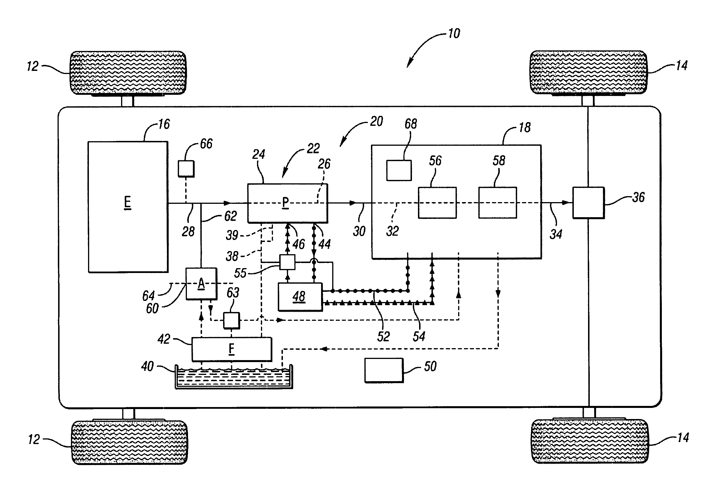
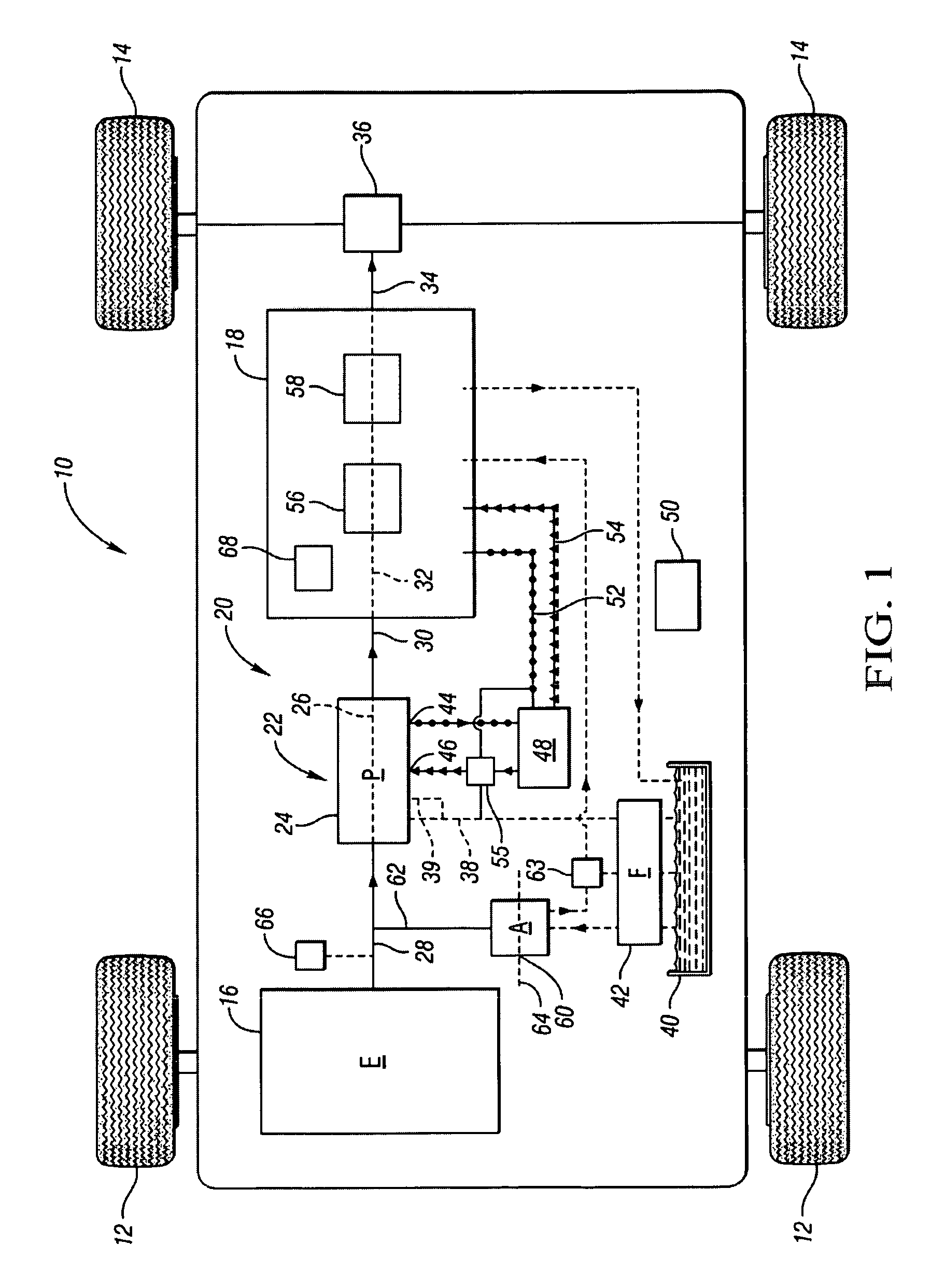
[0022]Referring to the drawings, wherein like reference numbers refer to like components, FIG. 1 shows a vehicle 10 having front wheels 12 and rear wheels 14. The rear wheels 14 are powered by an engine 16 via a transmission 18 such that the vehicle 10 is a rear wheel-drive vehicle. While in this embodiment, the transmission is a rear wheel-drive transmission, in other embodiments the transmission may be a front wheel-drive transmission. The engine 16 and transmission 18 are part of a powertrain 20. The powertrain 20 may be non-hybrid (i.e., having the engine 16 as the only source of driving power) or hybrid (i.e., including an additional source of driving power, such as one or more electric motor / generators, a fuel cell, or any other known hybrid power source).

[0023]The powertrain 20 further includes a hydraulic system 22 used for providing hydraulic pressure to the transmission 18 for cooling, lubrication, and clutch actuation. The hydraulic system 22 includes an on-axis fixed dis...


PUM


Abstract

A fixed displacement binary pump is provided for a powertrain on a vehicle. A hydraulic system is operatively connected with first and second discharge ports of the pump and is operable to alternately permit fluid flow through both discharge ports (i.e., full displacement or volumetric output of the pump) or permit flow through only the first discharge port (i.e., partial displacement or volumetric output of the pump). The pump may be packaged in a front support of the transmission. An auxiliary pump may be provided that is operable to supplement the output of the binary pump or to be used when the binary pump is off. A method of operating the binary pump and auxiliary pump is provided.

Description

TECHNICAL FIELD[0001]The invention relates to an on-demand binary fixed displacement hydraulic pump for a hydraulic system of a transmission in a vehicle powertrain and a method of operating the hydraulic system.BACKGROUND OF THE INVENTION[0002]The hydraulic system for a vehicle transmission serves important lubrication, cooling, and clutch actuation functions necessary for operation of the transmission. Generally, hydraulic pressure and flow within the hydraulic system is provided by an engine-driven hydraulic pump having a rotational speed proportional to engine speed. The hydraulic pump must be designed to meet peak demands, such as hydraulic fluid demand during shifting of the transmission, hot engine idle speed garage shifts, and, in certain transmissions, a hydraulic park mode in an electronic transmission range selector (ETRS) system. Additionally, hydraulic requirements of the transmission may still exist when the engine (and thus the engine-driven pump) is off, such as in a...

Claims


Application Information

Patent Timeline
Patent Type & Authority Patents(United States)
IPC IPC(8): F16D31/02
CPCF16H61/0025F16H61/0031
Inventor SCHULTZ, JOHN C.WILTON, DARYL A.MELLET, EDWARD W.
Owner GM GLOBAL TECH OPERATIONS LLC
Why Eureka
Try Eureka