Helical cutting insert with progressive cutting edge

a cutting edge and helical technology, applied in the field of cutting inserts, can solve the problems of wear of solid end mill cutters, small machine tools, and inability to use indexable inserts, and achieve the effects of less power and torque, smooth cutting action, and increased feed ra

Inactive Publication Date: 2006-12-14
KENNAMETAL INC
View PDF50 Cites 22 Cited by
  • Summary
  • Abstract
  • Description
  • Claims
  • Application Information

AI Technical Summary

Benefits of technology

[0007] To solve these problems, the present invention provides an improved cutter body that utilizes an indexable cutting insert design that has at least two indexable cutting edges. High positive axial and radial rake angles of the improved indexable cutting insert design uses less power and torque than conventional inserts, thereby allowing smoother cutting action and increased feedrates that would have previously stalled a smaller machine tool. In addition, the cutting insert of the invention can be used in larger cutters with an increased number of cutting edges to increase productivity on both small and large machine tools. Further, the only scrap is the cutting insert and not the entire cutter body, thereby minimizing production costs as compared to conventional designs.
[0008] The present invention comprises an indexable cutting insert that includes a flat back that is held in a mounting pocket of a cutter body. The mounting pocket can be designed for ease of manufacture and repeatability. Stub length tooling may be used for rigid setups and lower cost. The cutting insert is located in the mounting pocket on two outboard walls. The cutting insert is secured to the cutter body by use of a screw in a cross hole fashion. The face of the cutting insert has a helical cutting edge on two sides and can be indexed by rotating the cutting insert approximately 180 degrees. With the use of the cutting insert of the invention, the cutter body has a maximum core diameter for strength and rigidity, thereby minimizing tool deflection and extending the life of the cutter body. The cutting insert of the invention can be used in a variety of milling cutter body designs, such as end mill cutters, shell end mill cutters, or the like.

Problems solved by technology

Currently, the use of an indexable insert is not the first choice for small machine tools because the spindles on such small machines produce relatively lower horsepower and torque than larger machine tools.
Because current cutting insert designs need more power to cut effectively, small machine tools are typically relegated to using solid end mill cutters and shell end mill cutters.
However, solid end mill cutters and shell end mill cutters wear as they lose diameter, and if broken, can be entirely scraped.
In addition, the limited size of the cutters that can be used with indexable insert designs may result in a loss of productivity.

Method used


Image

  • Helical cutting insert with progressive cutting edge
  • Helical cutting insert with progressive cutting edge
  • Helical cutting insert with progressive cutting edge

Examples


Embodiment Construction

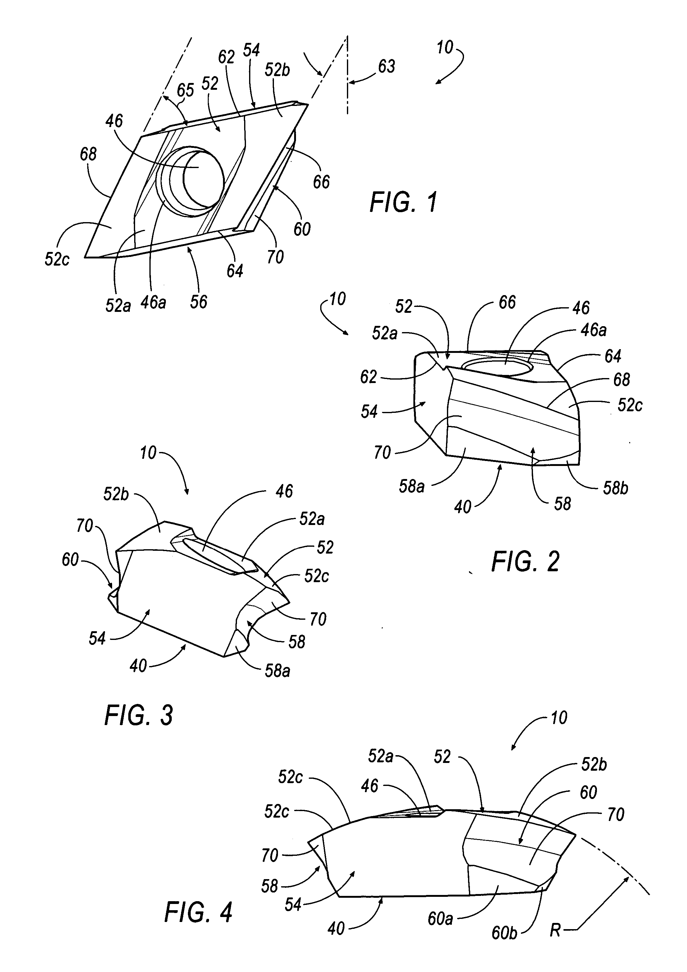
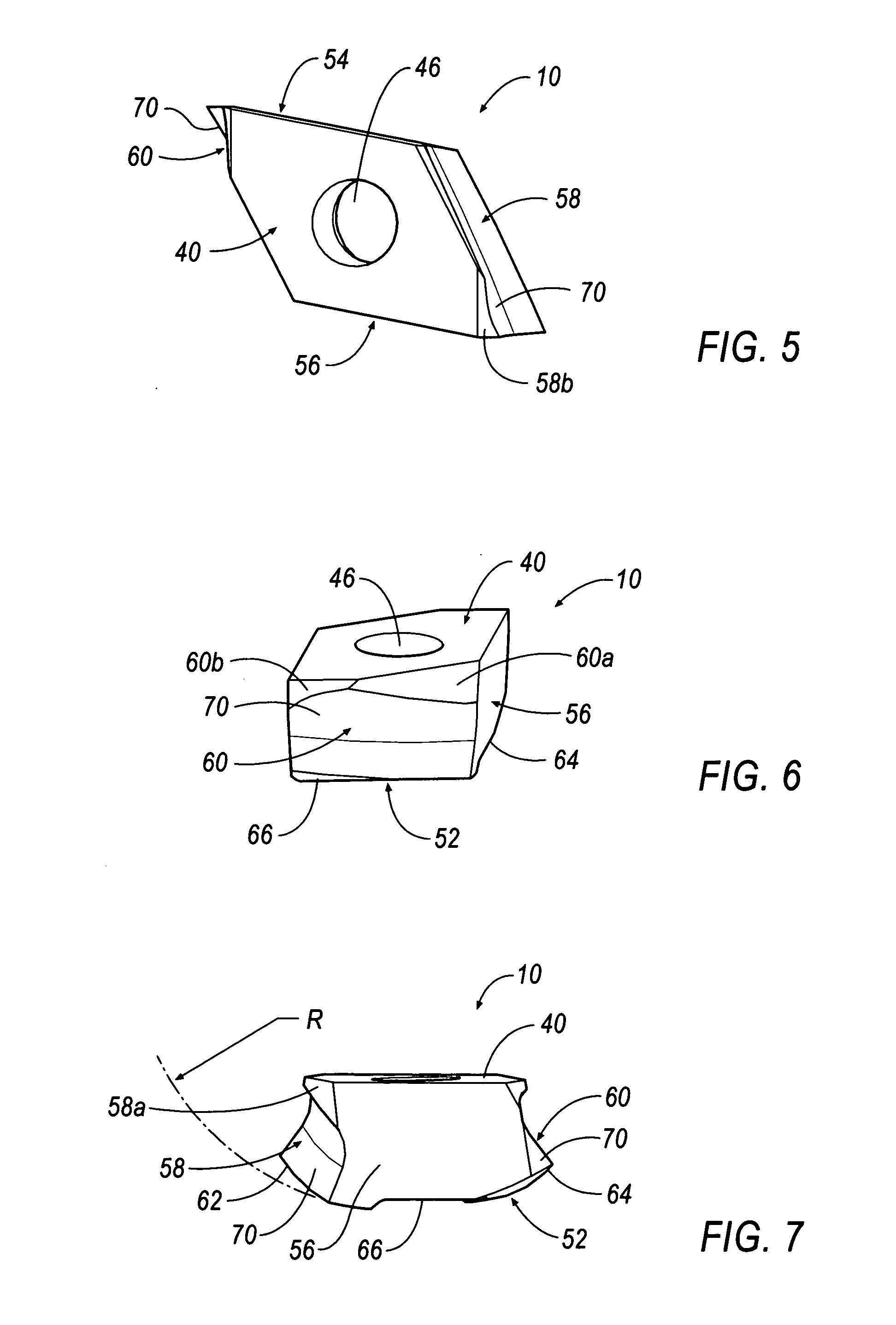
[0029] Referring now to FIGS. 1-8, a cutting insert 10 is shown according to an exemplary embodiment of the invention. The cutting insert 10 is generally diamond in shape and includes a front face or top surface 52, a pair of opposed side walls or surfaces 54 and 56, another pair of opposed side walls or surfaces 58 and 60, a base surface or back face 40. The top surface 52 includes a substantially flat central portion 52a, a first curved facet surface 52b, and a second curved facet surface 52c located on the opposite side of the central portion 52a. The side wall 58 includes a first substantially flat faceted surface 58a, and a second substantially flat faceted surface 58b having a smaller surface area than the faceted surface 58a. Similarly, the opposite side wall 60 includes a first substantially flat faceted surface 60a, and a second substantially flat faceted surface 60b having a smaller surface area than the faceted surface 60a. The other two side walls 54 and 56, and the back...


PUM

PropertyMeasurementUnit
angleaaaaaaaaaa
angleaaaaaaaaaa
angleaaaaaaaaaa

Abstract

An indexable, helical cutting insert includes at least one axial clearance slash extending from a bottom surface to one of said side walls forming a wiper on an edge of the axial clearance slash. In another embodiment, the cutting insert includes at least one inside cutting edge that extends outwardly a distance from the side wall. In another embodiment, the helical cutting insert includes at least one progressive cutting edge. In another embodiment, the cutting insert includes at least one helical cutting edge that is curved inwardly to enable the cutting insert to perform machining operations on cutters having different diameters.

Description

CROSS-NOTING TO RELATED APPLICATION [0001] This application is related to U.S. Pat. No. 6,773,209, filed May 31, 2002, entitled “Helical Insert and Cutter Bodies”, the entire contents of which are incorporated herein by reference.BACKGROUND OF THE INVENTION [0002] 1. Field of the Invention [0003] The present invention relates to cutters and cutting inserts used thereon, and in particular to a cutter system that includes a cutter body with tangentially-mounted, indexable, helical cutting inserts with multiple cutting edges. [0004] 2. Description of the Related Art [0005] Currently, the use of an indexable insert is not the first choice for small machine tools because the spindles on such small machines produce relatively lower horsepower and torque than larger machine tools. Because current cutting insert designs need more power to cut effectively, small machine tools are typically relegated to using solid end mill cutters and shell end mill cutters. However, solid end mill cutters a...

Claims


Application Information

Patent Timeline
Patent Type & Authority Applications(United States)
IPC IPC(8): B23C5/20
CPCB23C5/109B23C5/207B23C2200/085B23C2200/125B23C2200/203B23C2200/205Y10T407/23B23C2200/286B23C2200/367B23C2210/0485Y10T407/245Y10T407/1958Y10T407/235B23C2200/208B23C5/202
Inventor CRAIG, KAREN A.
Owner KENNAMETAL INC
Why Eureka
Try Eureka