Bone stabilization device

Active Publication Date: 2017-07-13
EXSOMED CORP
View PDF9 Cites 20 Cited by
  • Summary
  • Abstract
  • Description
  • Claims
  • Application Information

AI Technical Summary

Benefits of technology

[0008]In preferred embodiments, the device has a cutting structure at the tip of the second end, and a second cutting structure between the first

Problems solved by technology

Damage to the metacarpal bone may occur as a result of a sprain or fracture.
Problems with the nail are that, because it is not anchored in the bone, it can migrate through the metacarpal bone and into surrounding tissue.
Sometimes this can result in damage to soft tissue, such as a severed or damaged tendon or cartilage, and/or cause pain.
Another problem with the nail is that, because it can migrate, a second surgery is required to remove it.
Additionally, the proximal end of pins and nails can cause tendon irritation, tendon rupture or

Method used


Image

  • Bone stabilization device
  • Bone stabilization device
  • Bone stabilization device

Examples


Embodiment Construction

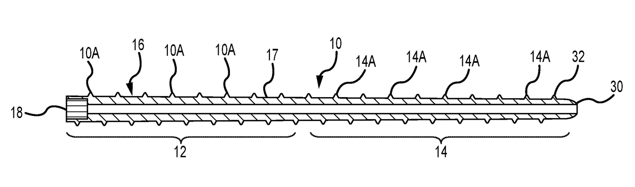
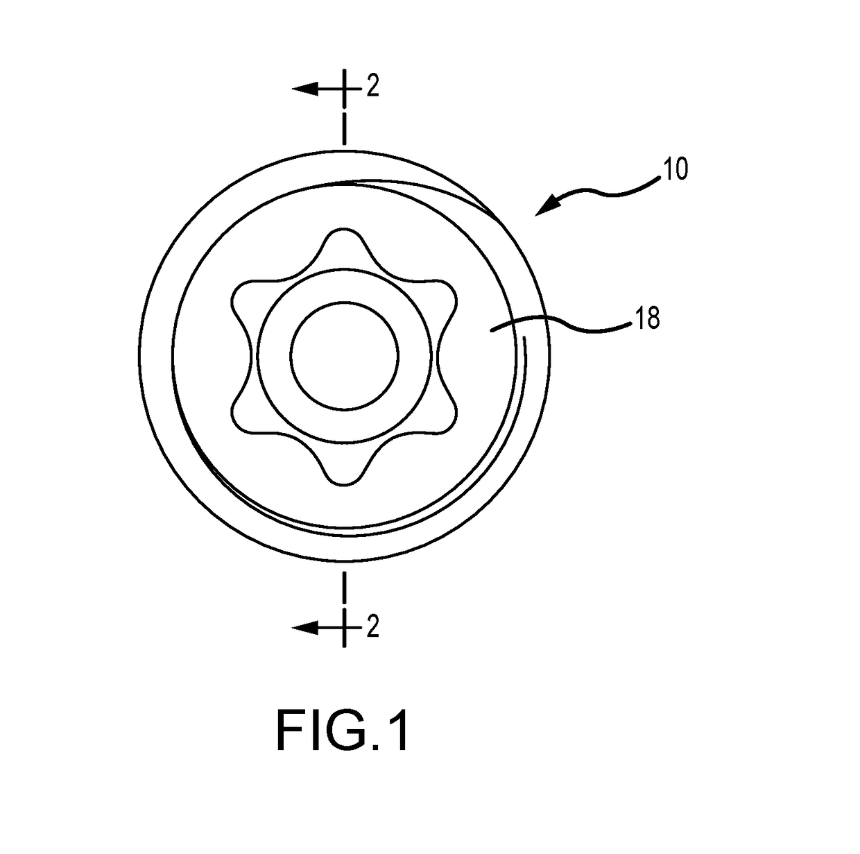
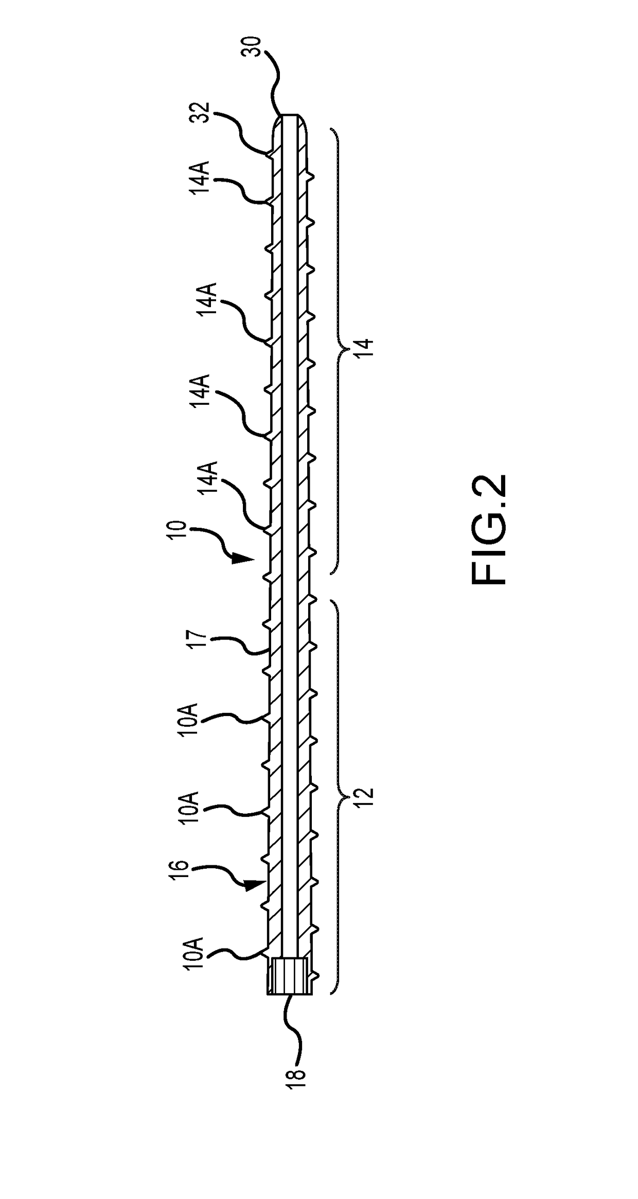
[0021]Turning now to the figures, where the purpose is to describe preferred embodiments of the invention and not to limit same, FIG. 1 shows an exemplary embodiment 10 of the invention. Device 10 may be formed of any suitable material, such as titanium steel, stainless steel or nitinol. Device 10 has a first (or proximal) section 12, a second (or distal) section 14, and a shaft 16 with an outer surface 17. Device 10 may be between 6.5 cm and 8 cm in length, or have a length of about 7 cm.

[0022]First section 12 has first threads 10A which preferably have a height of about 0.5 to 1 mm as mearured from outer surface 17, and a pitch of about 1 mm per revolution. A driving surface, or head, 18 is shown as being the same diameter of first section 12, but head 18 may have a different diameter or be of a different shape, such as triangular. Head 18 may accept any suitable driver configuration, such as a Torx drive, slotted, Pozidriv, Robertson, tri-wing, Torq-Set, SpannerHead, Triple Squar...


PUM


Abstract

A device and method for stabilizing a broken bone while it heals is disclosed. The device preferably has a (a) first (or proximal) section with a driving head, threads and a first diameter, and (b) second (or distal) section that is threaded and has a second diameter. The first section is preferably greater in diameter than the second section so that greater torque can be applied to tighten the device. The device may include one or more self-tapping structures to lessen the torque required to screw it into a bone.

Description

FIELD OF THE INVENTION[0001]The present invention relates to a device implantable in a bone to stabilize it while it heals, and which is particularly suitable for use in a metacarpal bone.BACKGROUND OF THE INVENTION[0002]The palm of the hand is made up of bones called metacarpals, and a metacarpal connects each finger and thumb to the hand. Each finger and thumb is formed of bones called phalanges. The connection of the phalanges to the metacarpals is called a “knuckle” joint or metacarpophalangeal joint (MCP joint), and acts like a hinge when the fingers or thumb are bent. In the metacarpal bones, the proximal portion and mid metacarpal portion is relatively narrower, and the distal portion is relatively wider with respect to both the internal medullary canal and external diameter.[0003]In each finger, there are three phalanges that are separated by two joints called the interphalangeal joints (IP joints). The proximal IP joint (PIP joint) is the one closest to the MCP joint. The o...

Claims


Application Information

Patent Timeline
IPC IPC(8): A61B17/86
CPCA61B17/864A61B17/8897A61B17/8615A61B17/8635A61B17/7291A61B17/8645A61B2017/00867A61F2/4241
Inventor CHAMPAGNE, LLOYD P.ZOLDOS, JOZEF
Owner EXSOMED CORP
Why Eureka
Try Eureka