Metal container

a container body and metal technology, applied in the field of metal container bodies, can solve the problems of difficult to achieve the formation of the screw thread on the container neck, and achieve the effects of shortening the neck, saving material, and simplifying the manufacture of the container body

Active Publication Date: 2018-01-16
CROWN PACKAGING TECH
View PDF26 Cites 20 Cited by
  • Summary
  • Abstract
  • Description
  • Claims
  • Application Information

AI Technical Summary

Benefits of technology

[0008]The invention provides several advantages. The closure is removed from the body simply by twisting and there is no need to provide a vacuum release device in the end wall of the closure.
[0009]It is not necessary to provide a screw thread on the container neck. This greatly simplifies manufacture of the container body and saves on material since a shorter neck can be provided.
[0010]Having only an annular layer of sealing compound on the end wall of the cap closure means that the sealing compound need not be moulded but can form under gravity. This uses less compound, greatly simplifies manufacture and removes the scrap generated in the compound moulding process.
[0011]Since the cap closure does not require lugs to engage a thread, a very small radial gap can be provided between the skirt of the closure and the neck of the container body. This reduces the risk of ingress of foreign matter, bugs, etc. and also increases resistance to accidental damage.
[0012]The absence of any threads on the cap means it can have reduced height, thus saving in material.
[0013]The torque required to open a container made in accordance with the invention is considerably less than typically required to open a threaded container. For example, the opening torque for a 51 mm closure has been reduced from about 3.4 Nm to only about 1.0 Nm. Reduction in the opening torque allows the use of fewer lubricants in the compound. These lubricants are one of the principle causes of migration into the food during processing. Thus, the new design also has benefits for food safety.

Problems solved by technology

Metal containers formed with a screw thread for connection to a closure are also known but the formation of the screw thread on the container neck is very difficult to achieve and tends to damage the internal coatings of the container which protect the metal of the container from the container contents.

Method used


Image

  • Metal container
  • Metal container
  • Metal container

Examples


Embodiment Construction

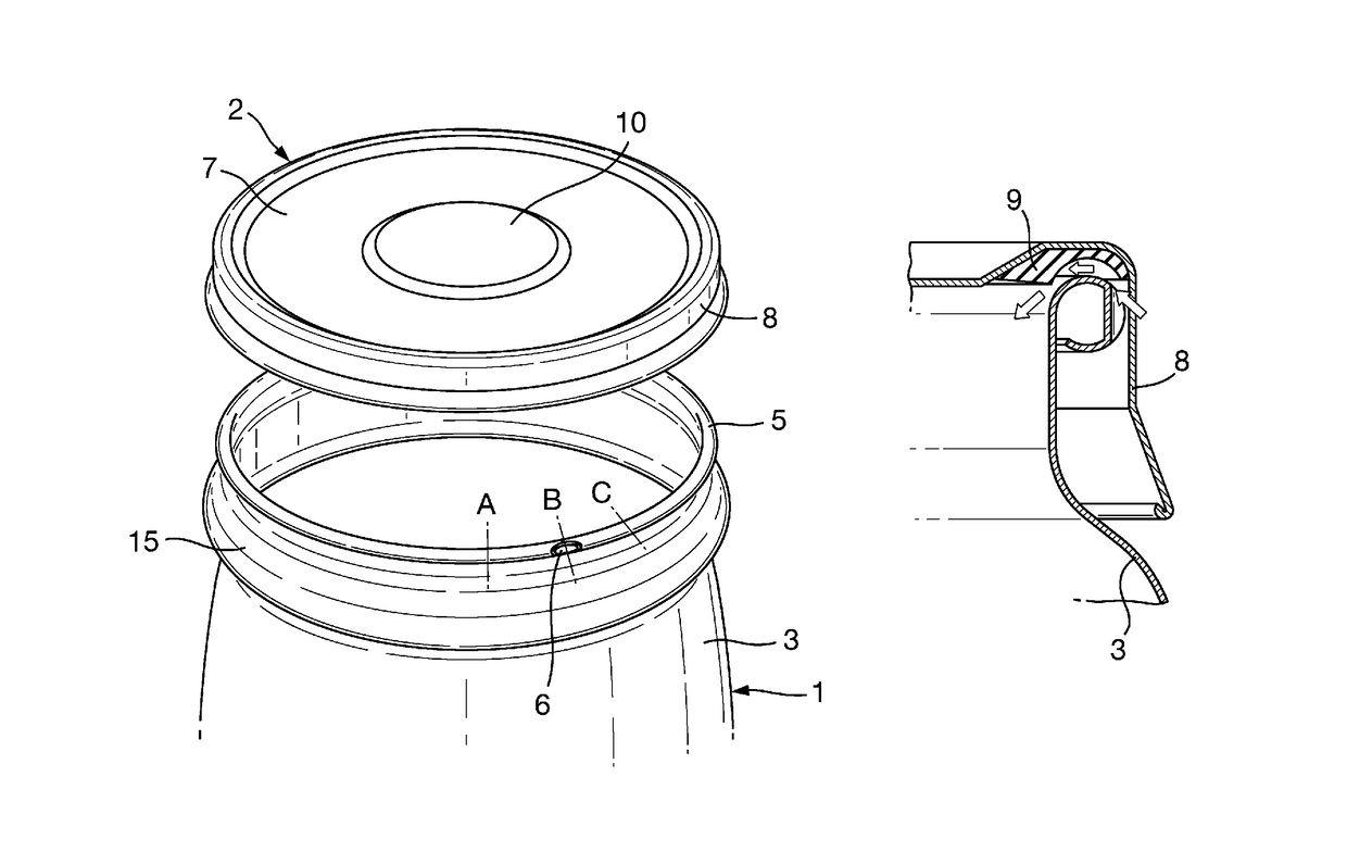
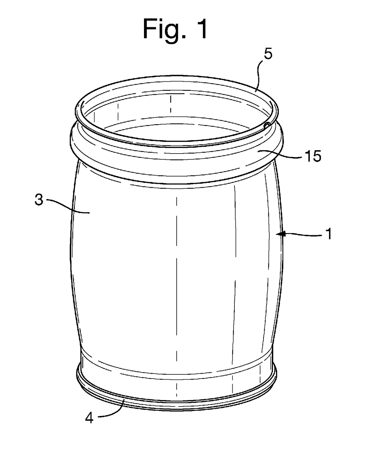
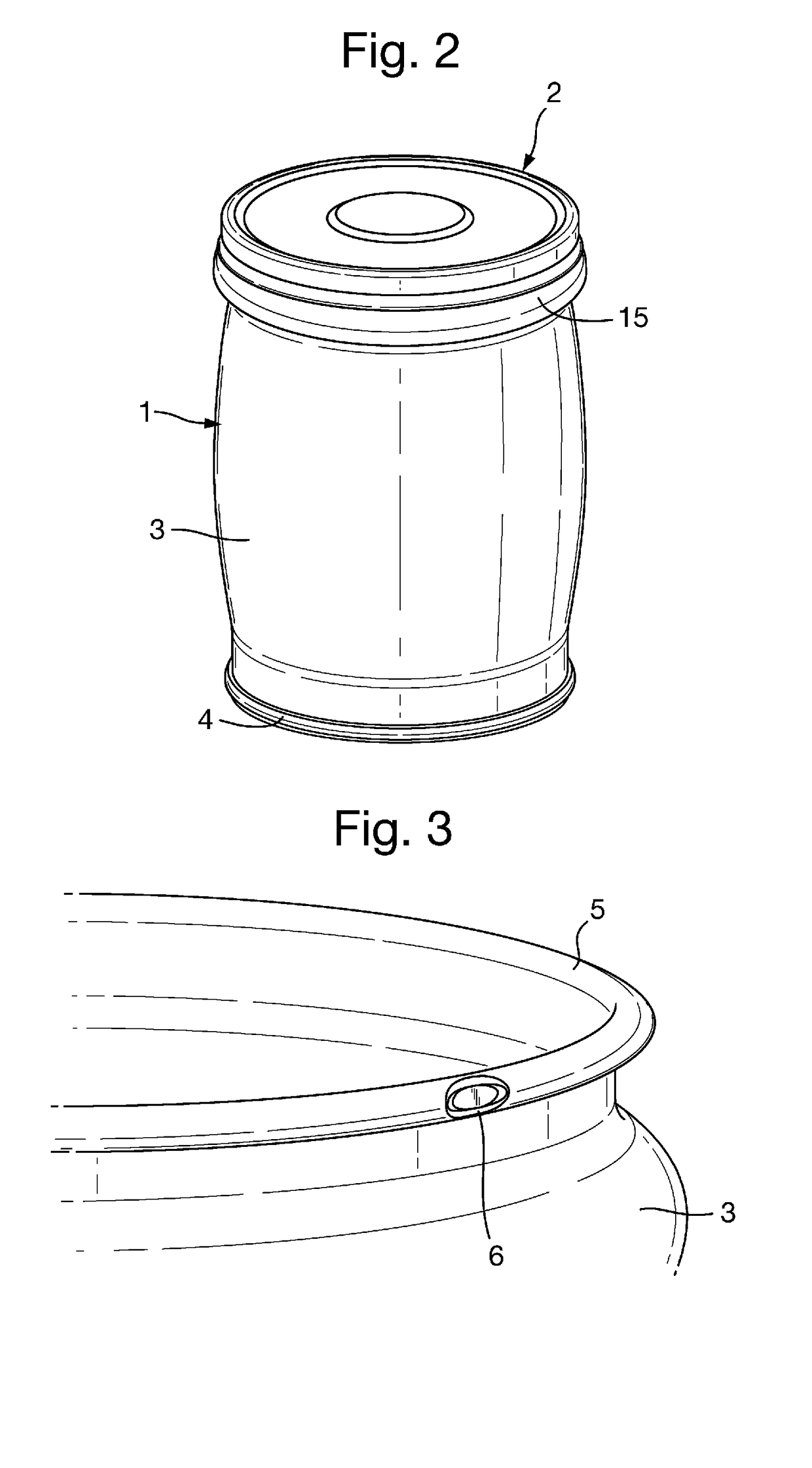
[0028]A container body 1 and a cap closure 2, both made of metal, are shown in the figures. The container body 1 has a side wall 3 made from a sheet of metal which is formed into a cylinder with the ends of the sheet overlapping slightly and welded together along a seam. This kind of manufacture is well known. The bottom end wall 4 of the container is seamed to the cylindrical side wall.

[0029]The upper end of the sidewall 3 has been rolled over outwardly to turn in the cut end of the side wall. The rolled over top of the end of the side wall forms a hollow annular bead or curl 5 which surrounds the upper open end of the container body to form the rim of the container, the upper surface of which provides an annular sealing surface. In an alternative (not shown) the top of the sidewall can be rolled over inwardly to form the annular bead. For example, a 73 mm diameter welded can body is made from 0.18 mm thick tinplate steel and has an upper bead or curl 5 with diameter of around 1.5 ...


PUM

PropertyMeasurementUnit
diameteraaaaaaaaaa
depthaaaaaaaaaa
diameteraaaaaaaaaa

Abstract

A metal container body 1 comprises a base and a generally cylindrical side wall 3. The top edge of the cylindrical side wall is rolled over to form a hollow annular bead 5 surrounding the upper open end of the container body and a notch 6 is formed at a circumferential point in the annular bead. The container body is for use with a releasable closure 2 formed with an end wall 7 and a depending skirt 8 and having an annular layer of sealing material 9 provided on the inside of the end wall adjacent the skirt. When the closure is pressed onto the container body, the annular bead engages the annular layer of sealing material and some of that material extends into the notch 6. The closure is held on the container only by the partial vacuum formed therein during processing of a food product in the container. After processing, the user opens the container by rotating the closure. Sealing material in the notch forces the closure to lift off from the container to break the seal and release the closure.

Description

CROSS-REFERENCE TO RELATED APPLICATIONS[0001]This application is the National Stage of International Application No. PCT / EP2013 / 059227, filed May 3, 2013, which claims the benefit of European application number 12167163.0, filed May 8, 2012, the disclosures of which are incorporated herein by reference in their entirety.TECHNICAL FIELD[0002]The invention relates to a metal container body for use with a releasable closure containing an annular layer of sealing compound.BACKGROUND ART[0003]A container comprising a metal can body having a generally cylindrical side wall with a top edge rolled over to form an annular bead surrounding the upper open end of the body is known for use with a press-on cap closure which is sealed to the can body and held in position solely by a vacuum which is formed in the head space above the product in the container during processing. The cap is formed with a vacuum release means comprising a small opening in the end wall of the closure which is normally c...

Claims


Application Information

Patent Timeline
Patent Type & Authority Patents(United States)
IPC IPC(8): B65D41/18B65D51/16B65D1/16B65D41/16B65D41/17B65D1/02B65D43/02B65D8/00
CPCB65D7/04B65D1/0223B65D1/165B65D41/165B65D43/0204B65D51/1688B65D41/17B65D2543/00953B65D2543/00425B65D2543/00546
Inventor MCGIRR, LAURA JANEELLISON, TRISTAN ROBERTRAMSEY, CHRISTOPHER PAUL
Owner CROWN PACKAGING TECH
Why Eureka
Try Eureka