Cooling apparatus

a technology of cooling apparatus and cooling chamber, which is applied in the direction of domestic cooling apparatus, lighting and heating apparatus, and semiconductor/solid-state device details. it can solve the problems of difficult cooling of components that do not produce enough heat to evaporate liquid

Active Publication Date: 2015-03-17
ABB (SCHWEIZ) AG
View PDF4 Cites 1 Cited by
  • Summary
  • Abstract
  • Description
  • Claims
  • Application Information

AI Technical Summary

Benefits of technology

[0008]Exemplary embodiments of the present disclosure solve the above-mentioned drawback by providing an efficient and reliable solution for cooling electric equipment.

Problems solved by technology

A drawback with a solution as described above is that components not producing sufficient heat to evaporate the liquid are difficult to cool.

Method used


Image

  • Cooling apparatus
  • Cooling apparatus

Examples


Embodiment Construction

[0008]Exemplary embodiments of the present disclosure solve the above-mentioned drawback by providing an efficient and reliable solution for cooling electric equipment.

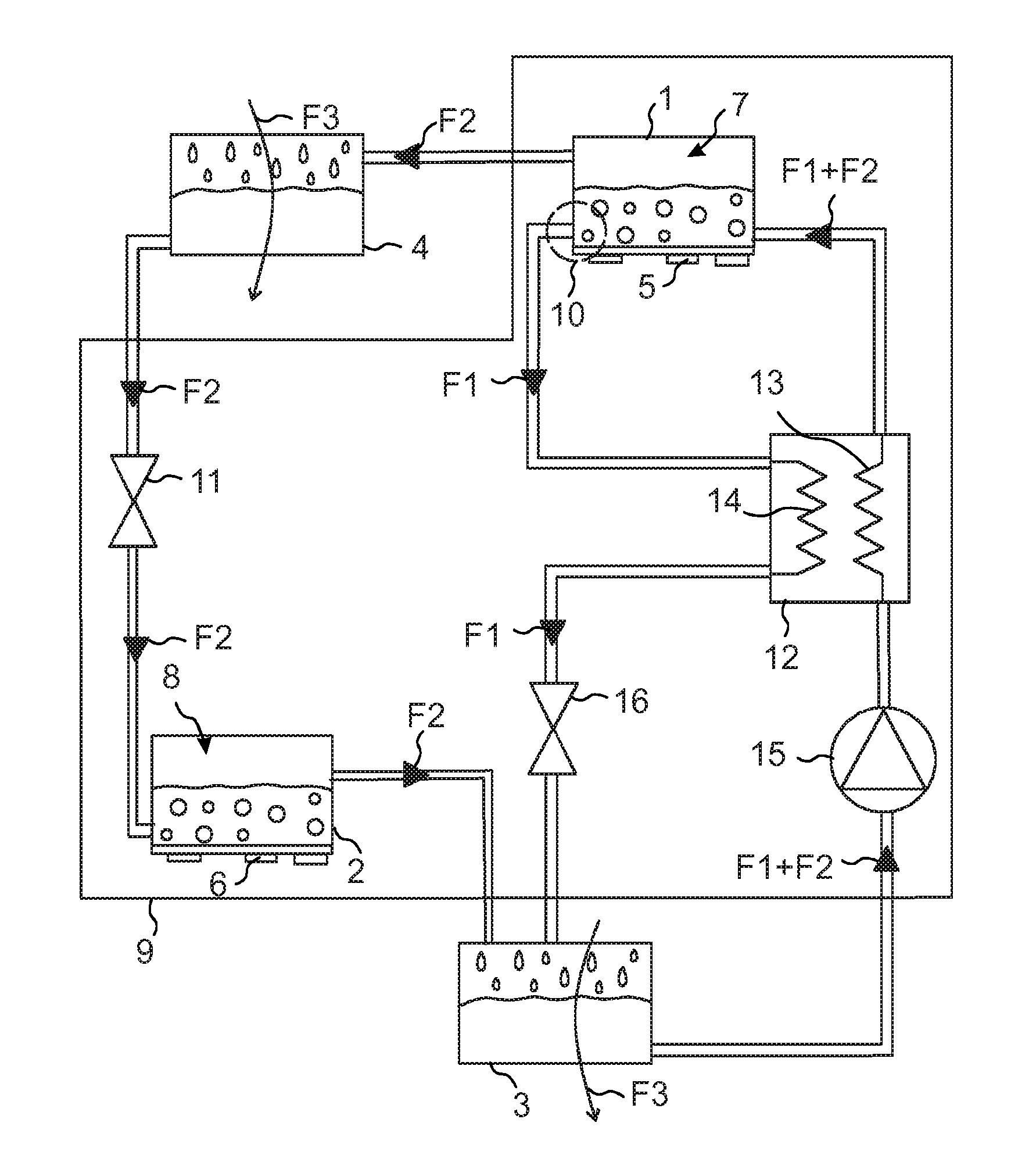
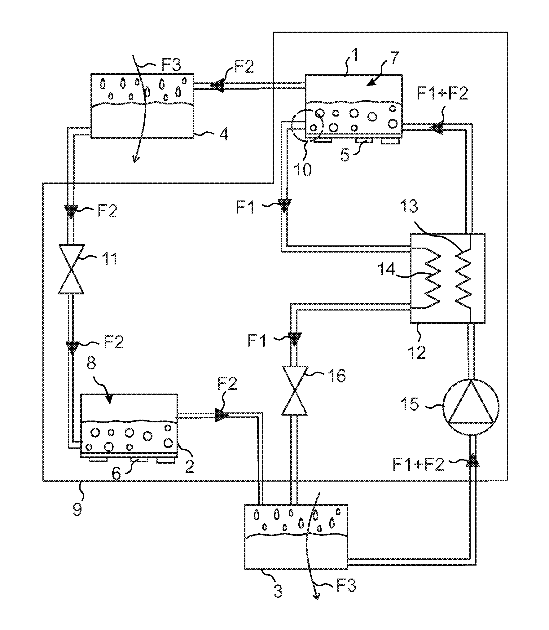
[0009]FIG. 1 is a block diagram of an exemplary embodiment of a cooling apparatus. The cooling apparatus includes a generator 1 with first electric components 5. The term “generator” refers to a heat exchanger cooling electric components, and which generates heat into the fluid in the fluid channel of the generator by passing on the heat load from the electric components to the fluid. The cooling apparatus also includes a evaporator 2 with second electric components 6. The term “evaporator” refers to a heat exchanger cooling electric components by evaporating fluid in the fluid channel of the evaporator with the heat load from the electric components. In the illustrated exemplary embodiment, it has by way of example been assumed that the first electric components 5 are attached (such as connected with thermal grease, ...


PUM


Abstract

A cooling apparatus for electric equipment includes a generator configured to receive a heat load from first electric components, a evaporator configured to receive a heat load from second electric components, a closed compartment enclosing the generator and evaporator, and a absorber transferring heat from heated fluid to the outside of the closed compartment. To obtain an efficient and reliable cooling apparatus, the cooling apparatus includes a first expansion device which reduces the pressure of the fluid, and forwards the fluid in a liquid state and with a lower pressure to the secondary cooling element, which transfers heat to the received fluid from the second electric components for evaporating the fluid.

Description

RELATED APPLICATION[0001]This application claims priority under 35 U.S.C. §119 to European Patent Application No. 13155426.3 filed in Europe on Feb. 15, 2013, the entire content of which is hereby incorporated by reference in its entirety.FIELD[0002]The present disclosure relates to a cooling apparatus for cooling electric equipment.BACKGROUND INFORMATION[0003]A known solution for cooling electric equipment involves evaporating a liquid in a cooling element which is used for transferring heat from electric components into a liquid in a fluid channel of the cooling element. The vaporized liquid is led to another cooling element where heat is transferred to a coolant such that liquid is again obtained, and this liquid is returned to the first cooling element.[0004]A drawback with a solution as described above is that components not producing sufficient heat to evaporate the liquid are difficult to cool.SUMMARY[0005]An exemplary embodiment of the present disclosure provides a cooling a...

Claims


Application Information

Patent Timeline
Patent Type & Authority Patents(United States)
IPC IPC(8): F25B27/00F25B15/00F25B15/06H01L23/00
CPCF25B15/00H01L23/00F25B27/00F25B15/06Y02B30/62H01L2924/0002H01L23/427Y02A30/27H01L2924/00
Inventor AGOSTINI, BRUNOAGOSTINI, FRANCESCOELOMAA, HEIKKISUNDELIN, JARIHABERT, MATHIEU
Owner ABB (SCHWEIZ) AG
Why Eureka
Try Eureka