Speed control drive circuit for blower motor

a technology of speed control and drive circuit, which is applied in the direction of motor/generator/converter stopper, dynamo-electric converter control, instruments, etc., can solve the problems of many very short pulses at the dc rail voltage, short rise time, winding insulation failure in the motor armature, etc., to reduce the stress on the transistor, avoid energy waste, and inherently compact

Inactive Publication Date: 2000-09-12
INT CONTROLS & MEASUREMENT
View PDF20 Cites 83 Cited by
  • Summary
  • Abstract
  • Description
  • Claims
  • Application Information

AI Technical Summary

Benefits of technology

It is another object to provide a speed control or driver circuit that achieves efficient operation of a blower motor over a wide range of blower speeds and air flow rates, but without the danger of overstressing the armature insulation.
It is a further object to provide a motor speed control or driver circuit that is reliable and efficient, and which can be easily controlled by the user, e.g., from the thermostat.
It is another object to provide a motor speed control or driver circuit that operates at great efficiency and at much reduced power requirements in low speed operation.
In this drive system, both pulse frequency and pulse amplitude are controlled in accordance with the blower motor speed, i.e., in accordance with the desired air flow rate. Unlike the PWM drive systems mentioned before, there is much reduced risk of creating high interturn voltages that can pierce the insulation. Also, because the transistors in the bridge inverter switch on and off only once per half cycle, the transistors spend very little time crossing their active regions, and this also reduces the stress on the transistors as compared with PWM ASD circuits.
The drive circuit acts to provide drive pulses in which the pulse amplitude, i.e., the DC voltage feed to the inverter, is increased or decreased in accordance with demand for more or less blower speed. The pulse rate or frequency is likewise controlled in accordance with the demand for more or less motor speed. The drive pulses have only one pulse for each half cycle of the drive wave, and thus avoid the high-frequency problems discussed above.
The drive circuit of this invention is of a simple, straightforward design. The circuit is inherently compact and is relatively inexpensive, and avoids energy waste.

Problems solved by technology

Unfortunately, the use of PWM can lead to other problems, including winding insulation failure in the motor armature.
This means that there are many very short pulses at the DC rail voltage, each with a very short rise time.
At the same time, the insulation in the motor's armature windings have a limited insulation strength, and the high frequency pulses that occur in these ASDs can overstress the interturn winding insulation.
This problem becomes exaggerated where there are multiple high frequency pulses for each half cycle of the drive wave.

Method used


Image

  • Speed control drive circuit for blower motor
  • Speed control drive circuit for blower motor
  • Speed control drive circuit for blower motor

Examples


Embodiment Construction

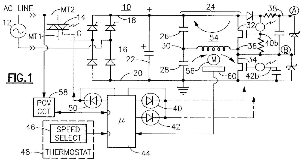
With reference to the Drawing, FIG. 1 is a circuit diagram of an illustrative embodiment of a pulse-amplitude modulated (PAM) and pulse rate modulated blower motor drive circuit 10. Here there is a single-phase AC voltage source 12, e.g., a nominal 120 volts AC at 60 Hz, for example, line power. For sake of simplicity, a single-phase system is illustrated here, but persons of ordinary skill could easily apply the principles of this invention to polyphase line power, and could apply the invention to a drive system for a three-phase AC induction motor, if desired. The AC source 12 is supplied through a triac 14 (here, a phototriac) to inputs of a full wave rectifier 16, which converts the voltage to direct current and applies it onto a positive rail 18 and a negative rail 20. In this case one AC conductor from the AC source 12 is connected to a main current terminal of the triac, and the other main current terminal is connected to one AC input of the rectifier 16. The other AC conduct...


PUM


Abstract

Drive circuit for a blower motor employs a microprocessor control element, a controlled rectifier to provide DC power at a controlled rail voltage, and an inverter employing a pair of switching transistors arranged as a bridge inverter or half-bridge inverter. The drive circuit operates over a range of blower speeds and varies both the frequency and amplitude of bipolar pulses that are applied to the blower motor armature.

Description

The present invention relates to drive circuits for powering AC motors, and is especially directed to a speed control circuit that generates bipolar pulses to power a motor, such as an AC induction motor. The invention is especially directed to an arrangement for controlling the air flow into an air conditioned space, with blower speed being controlled in accordance with air conditioning load, in a manner to conserve electrical energy when the blower is operated at operating speed or lower speed, and in a manner that avoids insulation breakdown to the blower motor.In HVAC systems, such as home air conditioning systems, it is often necessary to change the fan speed or blower speed to control the amount of air flow through the system evaporator coil. Cold, dry air is considerably heavier than warm moist air, and so during initial operation the blower has to operate at high speed to pump conditioned air, especially to higher floors. Then, when the comfort space or living space has cool...

Claims


Application Information

Patent Timeline
Patent Type & Authority Patents(United States)
IPC IPC(8): H02P25/02H02P25/04H02P7/00
CPCH02P25/04
Inventor KADAH, ANDREW S.
Owner INT CONTROLS & MEASUREMENT
Why Eureka
Try Eureka