

Attachment mechanisms employed to attach a rear housing section to a fiber optic housing, and related assemblies and methods
a technology of rear housing and fiber optic housing, which is applied in the direction of fibre mechanical structure, substation/switching arrangement details, instruments, etc., can solve the problems of space management and space management in a data center that become even more critical, and achieve the effect of reducing the downtime of the fiber optic network
Active Publication Date: 2015-04-14
CORNING OPTICAL COMM LLC
View PDF1244 Cites 26 Cited by
- Summary
- Abstract
- Description
- Claims
- Application Information
AI Technical Summary
Benefits of technology
The patent text describes attachment mechanisms for connecting different parts of fiber optic equipment. These mechanisms make it easy to attach and remove parts, which can save time and minimize downtime for the network. One example is a removable extension tray that can be easily attached and removed from the fiber optic housing. Another example is upgrading the capacity of the rear housing section by adding a second rear housing section that can be easily attached and removed. The technical effects of these mechanisms are improved efficiency and flexibility in adding or upgrading fiber optic cable connections.
Problems solved by technology
A common problem in telecommunications systems, and in particular with fiber optic telecommunications equipment, is space management.
Therefore, space management in a data center becomes even more critical.
Method used
View moreImage
Smart ImageViewing Examples

Examples
second embodiment
[0018]FIG. 4A is a side view of fiber optic equipment including the rear housing section of FIG. 1 attached to a 2U-sized fiber optic housing;
third embodiment
[0019]FIG. 4B is a side view of fiber optic equipment including the fiber optic housing of FIG. 4A attached to a second example of a rear housing section;
fourth embodiment
[0020]FIG. 4C is a side view of fiber optic equipment including the fiber optic housing of FIG. 4A attached to a third example of a rear housing section;
Login to View More PUM
| Property | Measurement | Unit |
|---|---|---|
| widths | aaaaa | aaaaa |
| widths | aaaaa | aaaaa |
| biasing force | aaaaa | aaaaa |
Abstract
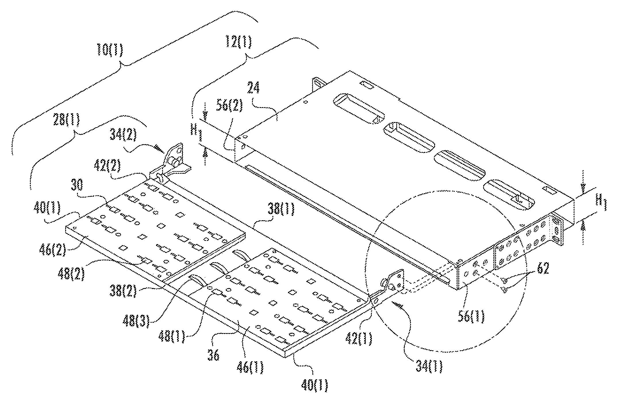
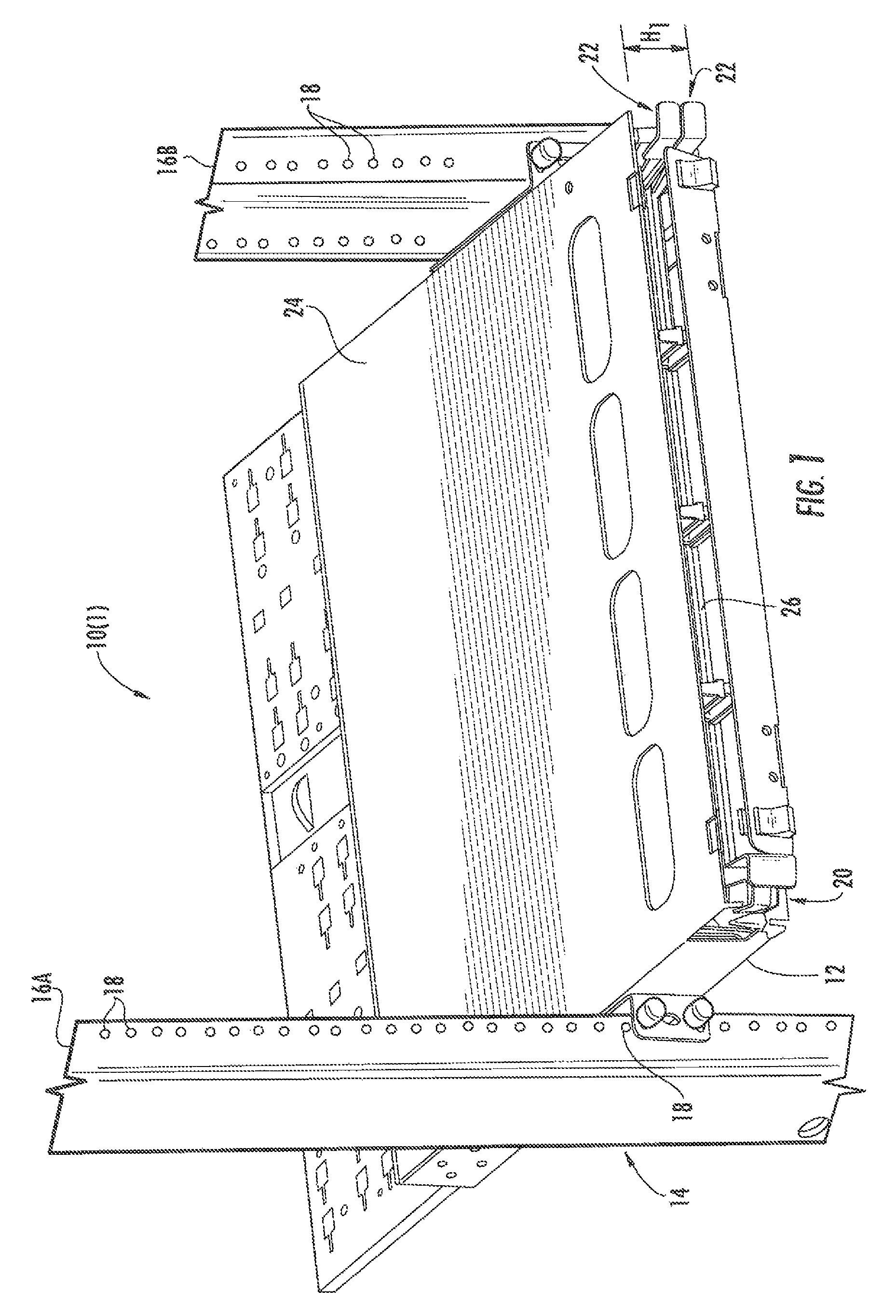
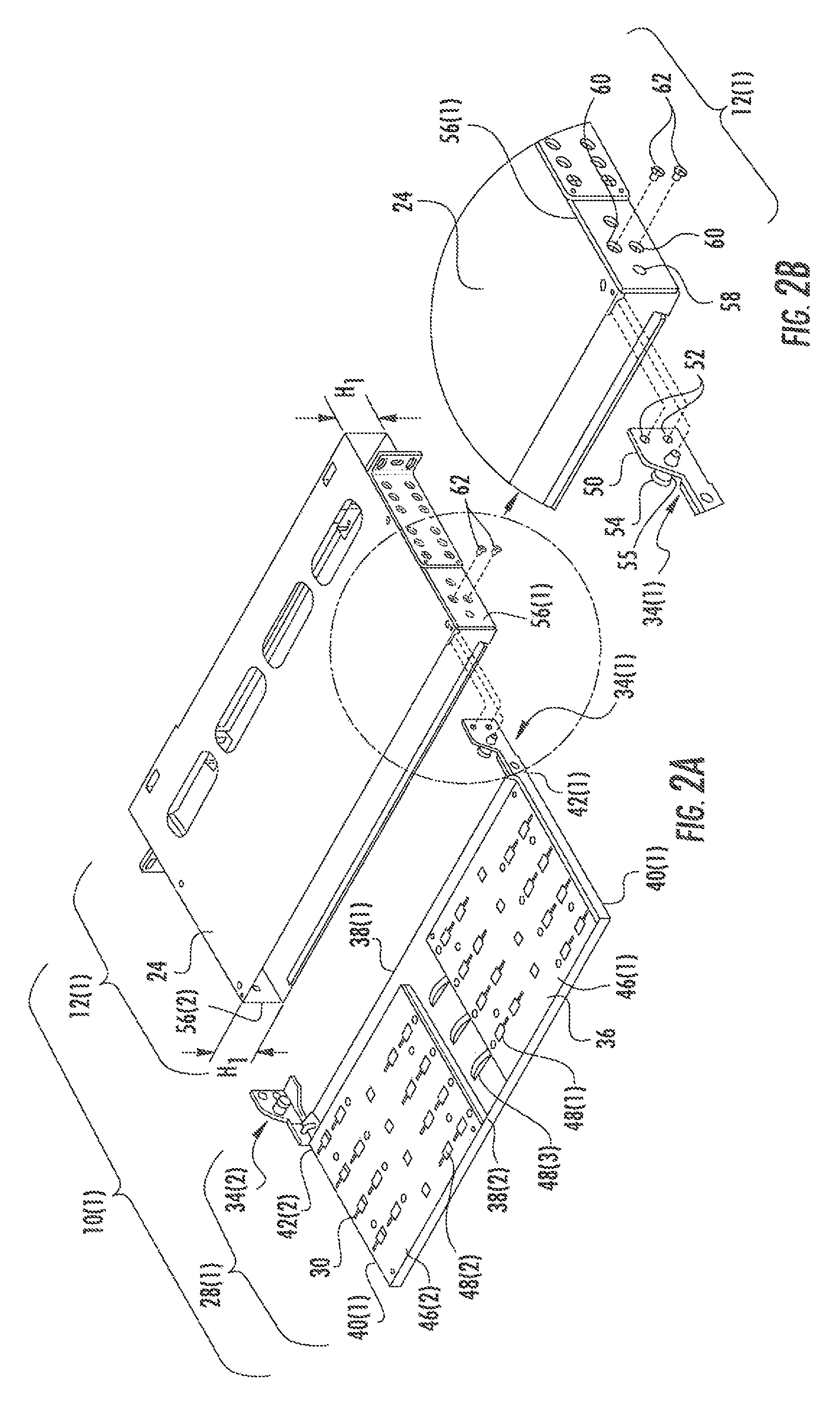
Attachment mechanisms configured to be employed to attach a rear housing section to a fiber optic housing, and related assemblies and methods are disclosed. The rear housing section and the fiber optic housing may be part of fiber optic equipment configured to support fiber optic connections of a fiber optic network. The attachment mechanism is configured to be attached and extend from the rear housing section of the fiber optic housing while maintaining the same installed U space of the housing. The attachment mechanism may include a spring plunger which may releasably maintain the rear housing section in a position to allow fasteners to removably attach the rear housing section to the fiber optic housing. In this manner, the rear housing section may be attached to and removed from the fiber optic housing in an efficient manner to minimize downtime for the fiber optic network.
Description
PRIORITY APPLICATION[0001]This application claims the benefit of priority under 35 U.S.C. §119 of U.S. Provisional Application Ser. No. 61 / 483,918 filed on May 9, 2011, the content of which is relied upon and incorporated herein by reference in its entirety.BACKGROUND OF THE DISCLOSURE[0002]1. Field of the Disclosure[0003]The present disclosure relates to fiber optic equipment for use in data centers and / or central offices, and more particularly to a rear housing section attached to a fiber optic chassis or housing in data centers and / or central offices.[0004]2. Technical Background[0005]Typical fiber optic telecommunication systems and networks include one or more telecommunications data centers and / or central offices. Large numbers of fiber optic and electrical cable connections that join various types of network equipment may be located in such facilities. The typical system also includes a number of outlying stations that extend the system into a network.[0006]This network equip...
Claims
Login to View More Application Information
Patent Timeline
 Patent Type & AuthorityPatents(United States)
IPC IPC(8): G02B6/00H02B1/01G02B6/44
CPCG02B6/4452G02B6/4455Y10T29/4973Y10T29/49826Y10T29/49947G02B6/44526G02B6/44524
InventorRAMIREZ, ERIKA GUADALUPE CHAPACOVARRUBIAS, JUAN MIGUEL GONZALEZCOWEN, ANDREW PHILIPMORALES, ARTURO PARRARHONEY, BRIAN KEITH
OwnerCORNING OPTICAL COMM LLC