
Keyboard apparatus for an electronic musical instrument

a technology of electronic musical instruments and keyboards, applied in the direction of instruments, electronic musical instruments, etc., can solve the problems of inability to provide a player with uniformity, inability to obtain ideal characteristics of reaction force, and inability to provide an ideal click sensation

Inactive Publication Date: 2015-05-26
YAMAHA CORP
View PDF6 Cites 6 Cited by
  • Summary
  • Abstract
  • Description
  • Claims
  • Application Information

AI Technical Summary

Benefits of technology

This configuration ensures that both white and black keys provide a similar feeling of click, enhancing the overall key touch experience by aligning the depression direction of the reaction force generation members with their axis lines at peak force, resulting in a more uniform and favorable key touch.

Problems solved by technology

However, the above-described conventional keyboard apparatus has a problem that the conventional keyboard fails to provide a player with a uniform key touch both on white keys and black keys, for the feeling of click perceived on a player's depression of a key varies between the white keys and the black keys.
Furthermore, since the placement of parts of a keyboard of an electronic musical instrument is strictly restricted, with structural restrictions being different between the white keys and the black keys, there are cases where the position of the pivot axis in the vertical direction or in the front-rear direction varies between the white keys and the black keys, or the position of the reaction force generation member in the front-rear direction varies between the white keys and the black keys.
As described in the above-described Examined Utility Model Application Publication, however, in a case where a reaction force against a depression of a key is applied by a rubber dome, ideal characteristics of reaction force cannot be obtained unless the rubber dome is depressed in a direction of the axis line of the rubber dome.
Particularly, the reaction force characteristics which provide an ideal feeling of click cannot be obtained unless the rubber dome is depressed in the axis line direction at the peak of the reaction force immediately before buckling of the rubber dome.
In the cases where the direction in which the reaction force generation member is depressed varies between the white keys and the black keys as described above, therefore, the keyboard apparatuses cannot provide players with uniform key touch on the white keys and the black keys, for the feeling of click varies between the white keys and the black keys.

Method used


Image

  • Keyboard apparatus for an electronic musical instrument
  • Keyboard apparatus for an electronic musical instrument
  • Keyboard apparatus for an electronic musical instrument

Examples


first embodiment

a. First Embodiment

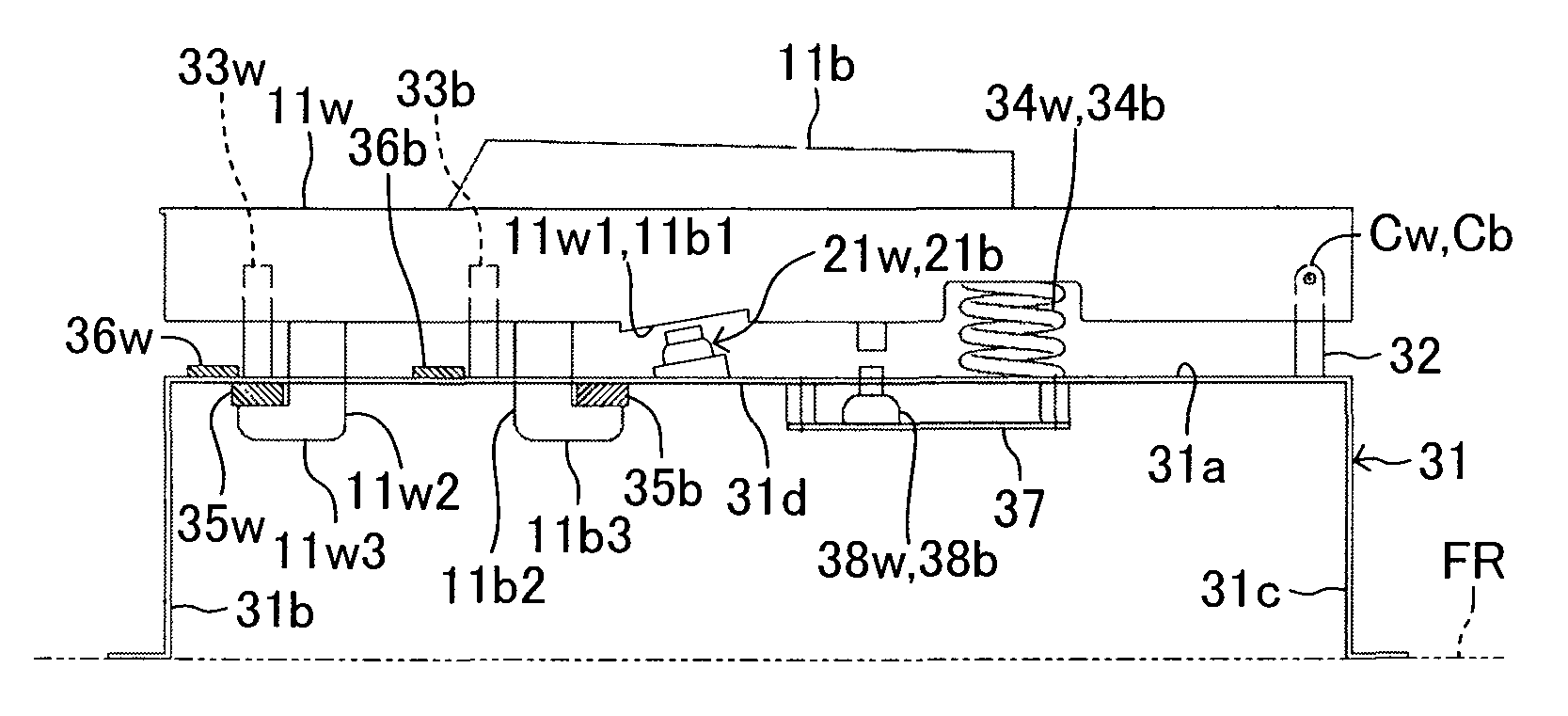
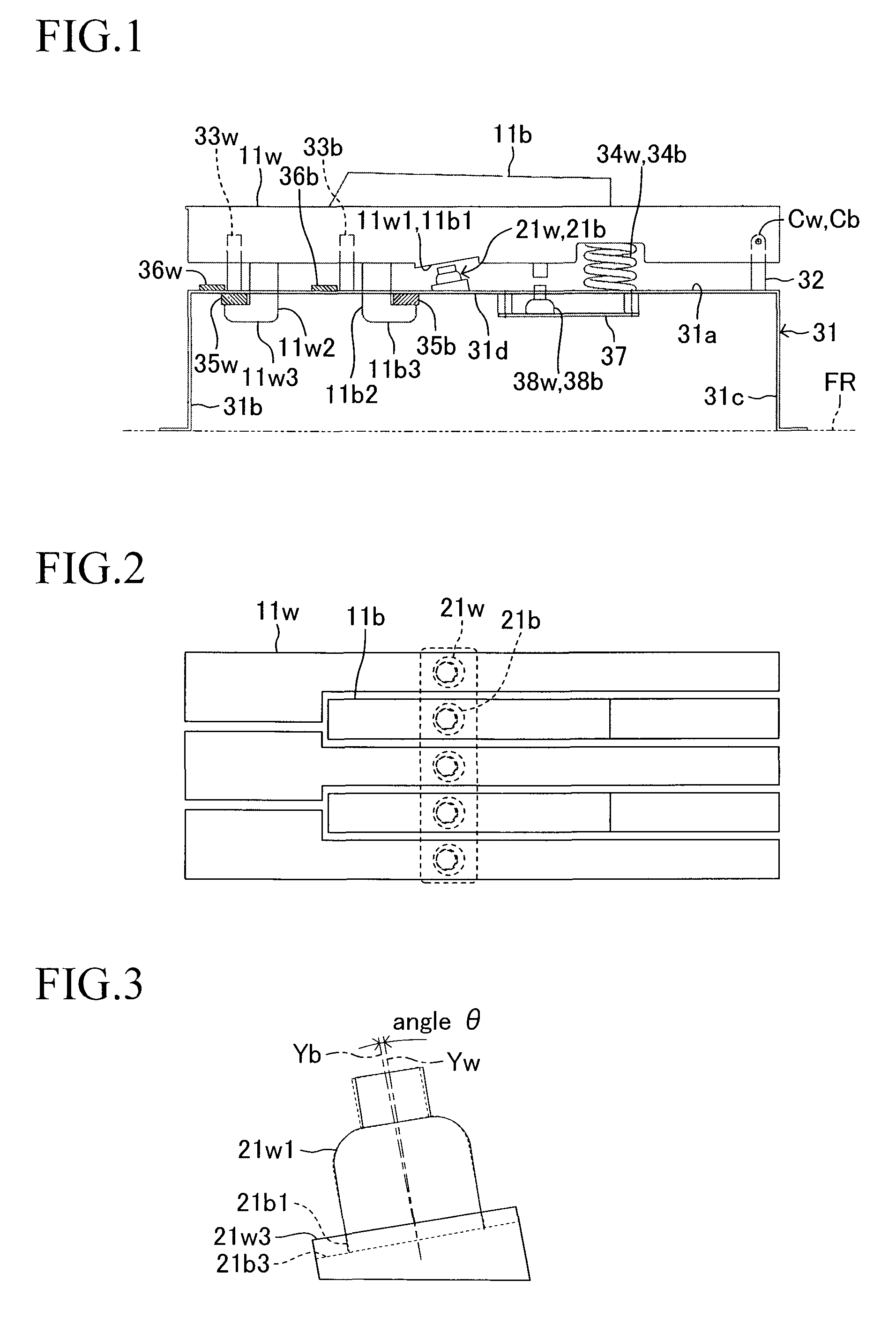
[0031]The first embodiment of the present invention will now be described with reference to the drawings. FIG. 1 is a schematic side view indicative of a keyboard apparatus according to the first embodiment seen from the right. FIG. 2 is a schematic top view of the keyboard apparatus. In the drawings of the present invention, the front-rear direction of the keyboard apparatus is defined as the lateral direction, and the vertical direction of the keyboard apparatus is defined as the vertical direction.

[0032]The keyboard apparatus has a plurality of white keys 11w and a plurality of black keys 11b which are to be depressed and released by a player. The keyboard apparatus also has a plurality of reaction force generation members 21w, 21b each exerting a reaction force against a player's depression of its corresponding key. The white key 11w is long in the front-rear direction, has a U-shaped cross-section which is open downward, and is located on a flat upper plate p...

second embodiment

b. Second Embodiment

[0064]The first embodiment and its modifications are configured such that the white key 11w and the black key 11b are provided with the depression portion 11w1 and 11b1, respectively, while the reaction force generation members 21w and 21b are fastened to the supporting portion 31d provided on the upper plate portion 31a of the key frame 31. In the first embodiment and its modifications, furthermore, by the depression of the white key 11w and the black key 11b, the top portions 21w2 and 21b2 of the reaction force generation members 21w and 21b are depressed with the depression portion 11w1 and 11b1, respectively. Instead of such a configuration, however, the reaction force generation members 21w and 21b may be provided on the white key 11w and the black key 11b, respectively. FIG. 12 indicates a keyboard apparatus according to the second embodiment in which the reaction force generation members 21w and 21b are provided on the white key 11w and the black key 11b, ...

third embodiment

c. Third Embodiment

[0071]Next, the third embodiment in which pivoting bodies which pivot in conjunction with pivoting of the white key 11w and the black key 11b depress the reaction force generation members 21w and 21b will be explained. FIG. 13 indicates a keyboard apparatus according to the third embodiment. The keyboard apparatus has hammers 41w and 41b which are the above-described pivoting bodies such that the hammers 41w and 41b correspond to the white key 11w and the black key 11b, respectively.

[0072]The hammers 41w and 41b are supported by hammer supporting members 42 provided for the respective white key 11w and black key 11b so that the hammers 41w and 41b can pivot. Each of the hammer supporting member 42 extends downward from the undersurface of the upper plate portion 31a such that the hammer supporting member 42 is situated at the middle of the white key 11w and the black key 11b in the front-rear direction. The hammers 41w and 41b are formed of base portions 41w1 and ...


PUM


Abstract

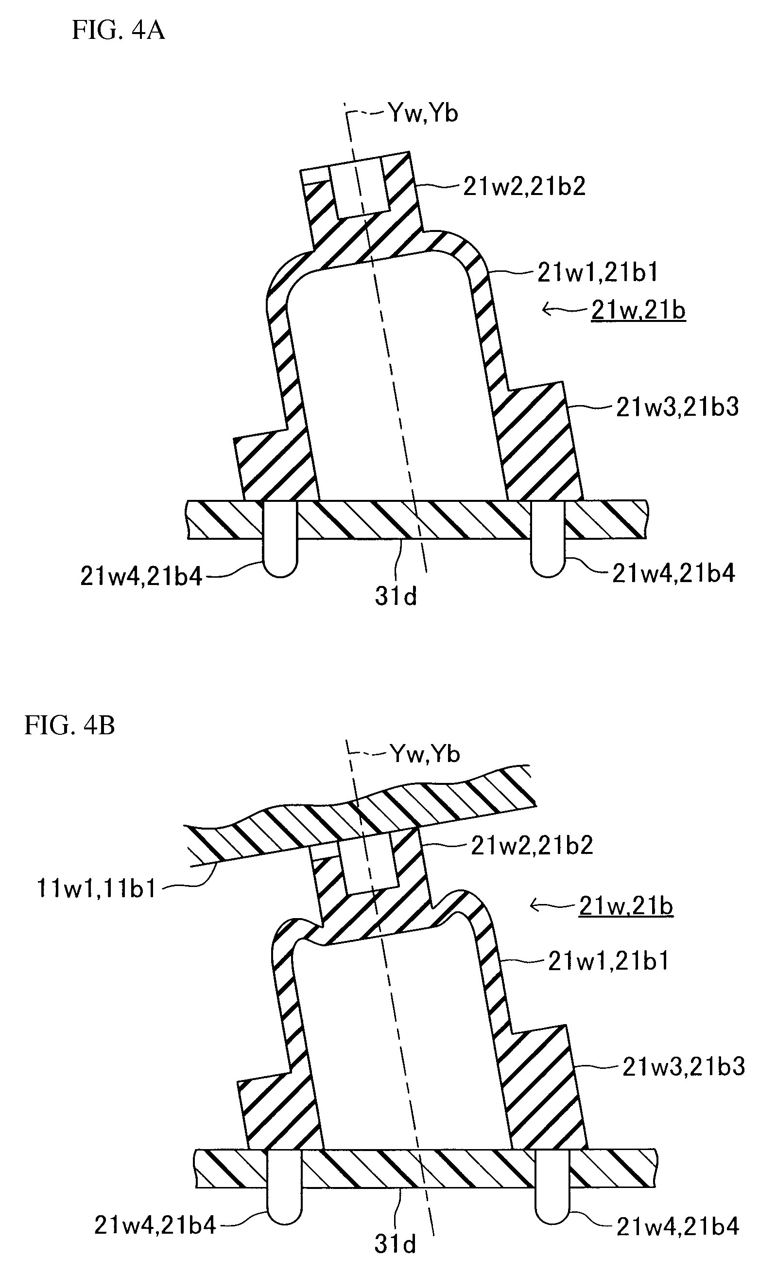
Reaction force generation members 21w, 21b are made of elastic body to be shaped like domes, respectively, so that the reaction force generation members 21w, 21b can be elastically deformed by depression exerted in directions of axis lines Yw, Yb, respectively, to increase their respective reaction forces from the beginning with the increasing amount of elastic deformation to buckle after respective peaks of the reaction forces to reduce the respective reaction forces. By varying the directions of the axis lines Yw, Yb of the reaction force generation members between a white key 11w and a black key 11b, the respective directions in which the reaction force generation members 21w, 21b are depressed at the peaks of the reaction forces are made close to the directions of the axis lines Yw, Yb of the reaction force generation members 21w, 21b, respectively.

Description

BACKGROUND OF THE INVENTION[0001]1. Field of the Invention[0002]The present invention relates to a keyboard apparatus for an electronic musical instrument, the keyboard apparatus having reaction force generation members for generating a reaction force by elastically deforming in response to a player's operation.[0003]2. Description of the Related Art[0004]Conventionally, there are keyboard musical instruments such as electronic organs and electronic pianos having rubber-dome reaction force generation members for exerting reaction force against the depression of keys. For example, Japanese Examined Utility Model Application Publication No. 7-49512 discloses a keyboard apparatus having a reaction force generation member (let-off element) on a key frame (shelf board) which supports a key located above the key frame so that the key can pivot. The reaction force generation member is elastically deformed, by being depressed by the key depressed by a player, to generate a reaction force. A...

Claims


Application Information

Patent Timeline
Patent Type & Authority Patents(United States)
IPC IPC(8): G10H1/32G10H1/34
CPCG10H1/34G10H1/346
Inventor OSUGA, ICHIROHARIMOTO, HIROSHI
Owner YAMAHA CORP
Learn More