Battery voltage detector having pull-up resistor

a pull-up resistor and detector technology, applied in the field of battery voltage detectors, can solve the problems of reducing the precision of cell balance control in some cases

Active Publication Date: 2015-06-02
HITACHI ASTEMO LTD
View PDF13 Cites 10 Cited by
  • Summary
  • Abstract
  • Description
  • Claims
  • Application Information

AI Technical Summary

Benefits of technology

[0010]To solve the above problem, a battery voltage detector according to one aspect of the present invention includes, but is not limited to: a voltage detection circuit; and a voltage processor. The voltage detection circuit includes, but is not limited to: a capacitor configured to be charged by a battery cell; a pair of output terminals; an output switch; and a voltage processor. While the capacitor is charged, the output switch is configured to be off-state and insulate the capacitor from the pair of the output terminals. After the capacitor is charged, the output switch is configured to be on-state and connect the capacitor to the pair of the output terminals. The voltage processor is configured to obtain, as a cell voltage, a voltage between the output terminals of the voltage detection circuit while the output switch is on-state. A high-potential output terminal of the pair of the output terminals is connected to a power line via a pull-up resistor.
[0009]The present invention has been made in view of the above situations. An object of the present invention is to provide a battery voltage detector that reduces drift errors caused by variations with time of resistance values of various resistances included in the cell voltage detection circuit, thereby enhancing precision of detecting a cell voltage.

Problems solved by technology

Consequently, a precise cell voltage cannot be obtained, thereby causing a decrease in the precision of cell balance control in some cases.

Method used


Image

  • Battery voltage detector having pull-up resistor
  • Battery voltage detector having pull-up resistor
  • Battery voltage detector having pull-up resistor

Examples


Embodiment Construction

[0016]The present invention will now be described herein with reference to illustrative embodiments. The accompanying drawings explain a battery voltage detector. The size, the thickness, and the like of each illustrated portion might be different from those of each portion of an actual battery voltage detector.

[0017]Those skilled in the art will recognize that many alternative embodiments can be accomplished using the teachings of the present invention and that the present invention is not limited to the embodiments illustrated herein for explanatory purposes.

[0018]Hereinafter, an embodiment of the present invention is explained with reference to the drawings.

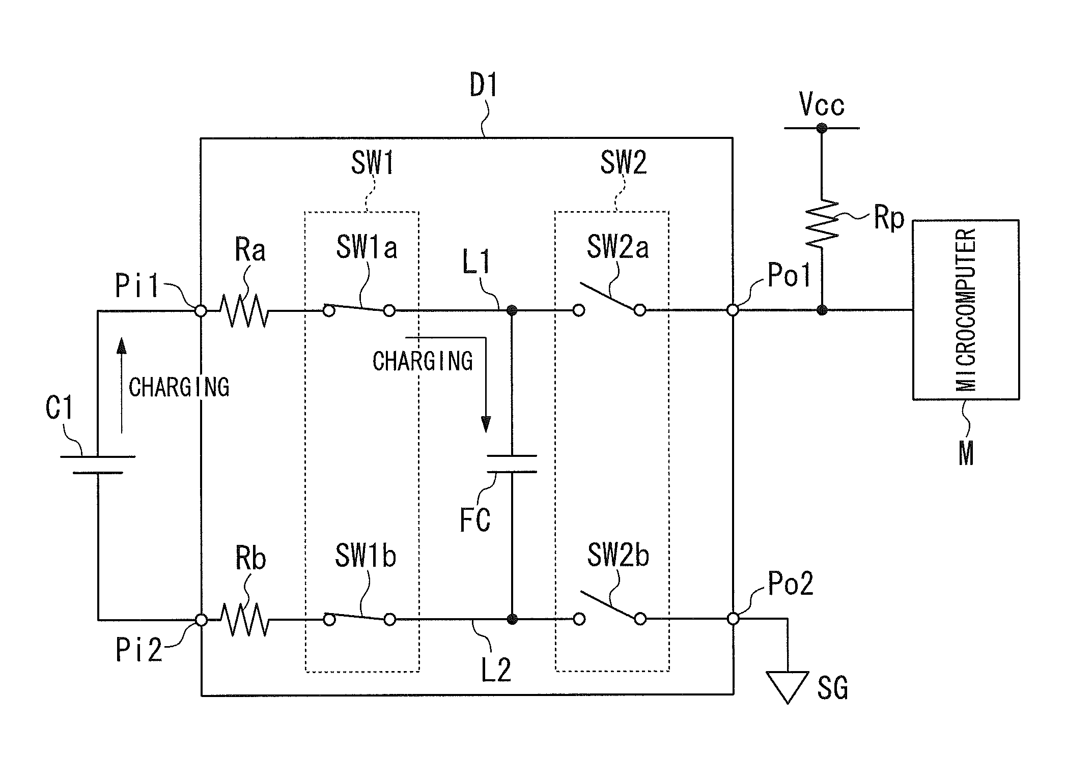
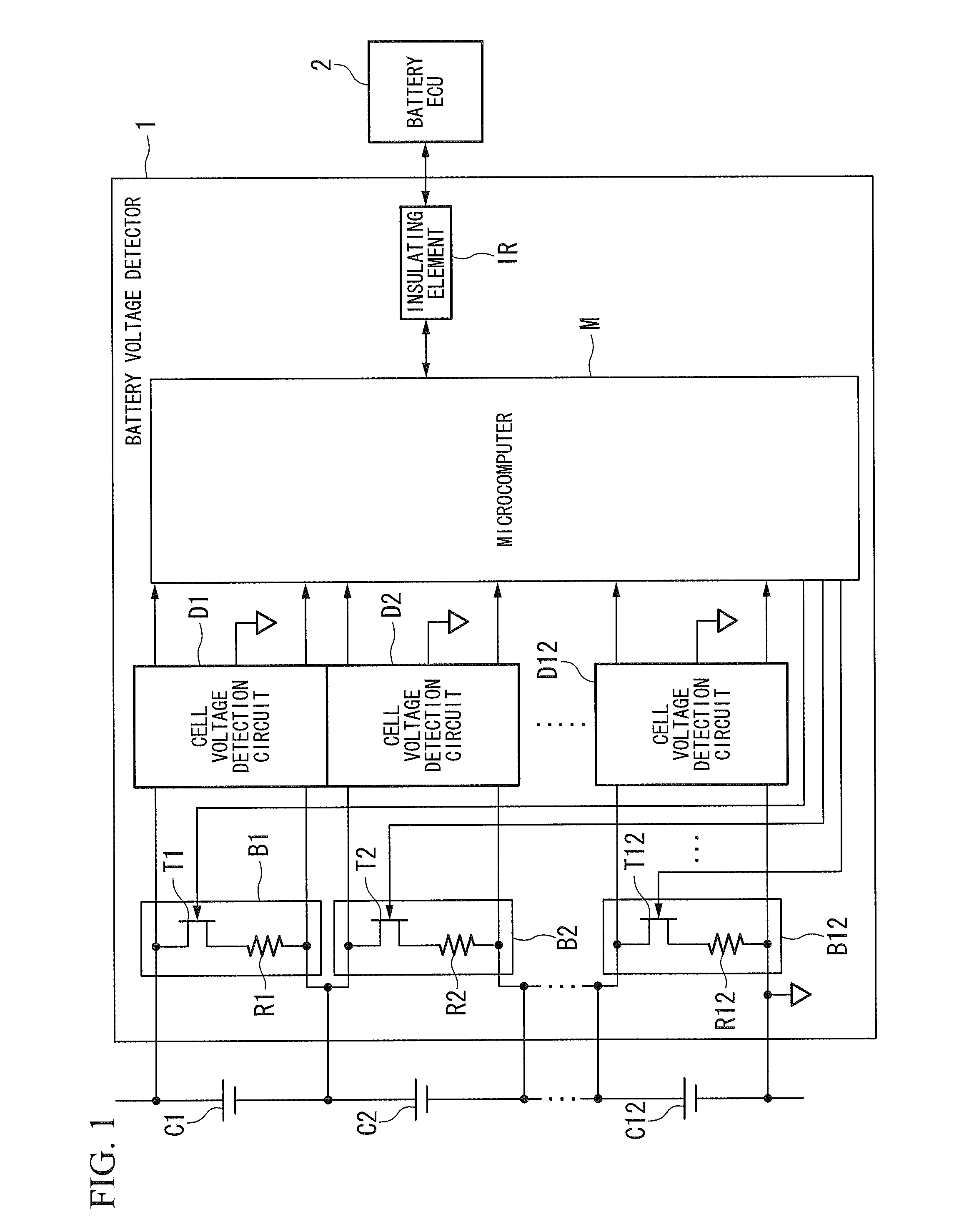
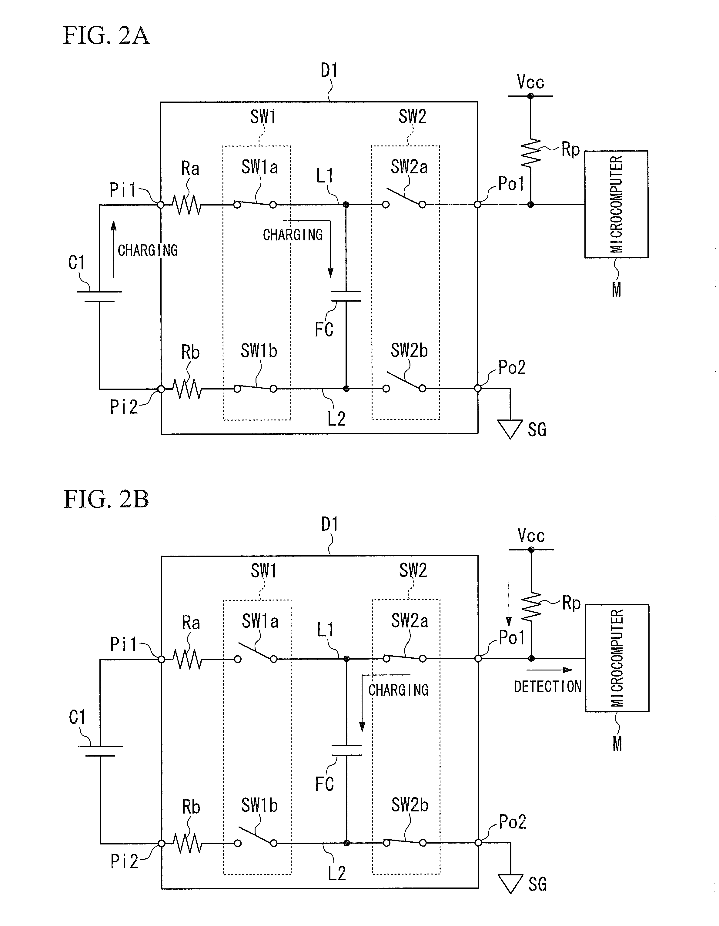
[0019]FIG. 1 schematically illustrates a battery voltage detector 1 according to the present embodiment. As shown in FIG. 1, the battery voltage detector 1 is an ECU (Electronic Control Unit) that detects cell voltages of twelve battery cells C1 to C12 included in a battery and performs voltage balance control on the battery c...


PUM


Abstract

A battery voltage detector includes, but is not limited to: a voltage detection circuit; and a voltage processor. The voltage detection circuit includes, but is not limited to: a capacitor configured to be charged by a battery cell; a pair of output terminals; an output switch; and a voltage processor. While the capacitor is charged, the output switch is configured to be off-state and insulate the capacitor from the pair of the output terminals. After the capacitor is charged, the output switch is configured to be on-state and connect the capacitor to the pair of the output terminals. The voltage processor is configured to obtain, as a cell voltage, a voltage between the output terminals of the voltage detection circuit while the output switch is on-state. A high-potential output terminal of the pair of the output terminals is connected to a power line via a pull-up resistor.

Description

BACKGROUND OF THE INVENTION[0001]1. Field of the Invention[0002]The present invention relates to a battery voltage detector.[0003]Priority is claimed on Japanese Patent Application No. 2011-075305, filed Mar. 30, 2011, the content of which is incorporated herein by reference.[0004]2. Description of the Related Art[0005]As known, a vehicle, such as an electric car or a hybrid car, is provided with a motor, and a high-voltage and high-capacity battery that supplies power to the motor. The battery includes multiple battery cells connected in series. The battery cell includes a lithium-ion battery, a nickel-metal hydride battery, or the like. In related art, a voltage balance control of monitoring and equalizing cell voltages of the battery cells is performed to maintain the performance of the battery.[0006]It is mainstream to use a flying-capacitor-type voltage detection circuit in order to detect a cell voltage because dedicated insulating power or insulating elements are unnecessary ...

Claims


Application Information

Patent Timeline
Patent Type & Authority Patents(United States)
IPC IPC(8): H02J7/00G01R19/00G01R31/36H02J7/02
CPCG01R31/3658G01R31/362G01R31/3835G01R31/396
Inventor TSUCHIYA, SHINGOKAMATA, SEIJI
Owner HITACHI ASTEMO LTD
Why Eureka
Try Eureka