Hinged table brake shoe

a brake shoe and hammer technology, applied in the direction of drum brakes, brake types, brake members, etc., can solve the problems of uneven braking force applied, uneven braking force application, inconsistent brake dynamics, control and performance of drum brakes, etc., to achieve more consistent brake dynamics, control and performance

Active Publication Date: 2015-06-23
BENDIKS SPAJSER FAUNDEJSHN BREJK LLK
View PDF32 Cites 2 Cited by
  • Summary
  • Abstract
  • Description
  • Claims
  • Application Information

AI Technical Summary

Benefits of technology

[0008]The present invention relates to a brake. In particular, the invention relates to an improved brake shoe for a drum brake that enables more consistent brake dynamics, control and performance as compared to conventional brakes.
[0010]A brake assembly in accordance with one embodiment of the present invention includes a brake spider having a central aperture configured to receive an axle extending therethrough. The brake further includes a first brake shoe having a first end coupled to the brake spider through a first anchor pin. The first brake shoe includes an arcuate brake table defining a radially outer side configured to receive a first brake lining and a radially inner side opposite the radially outer side. The brake table further defines first and second sleeves proximate a first end of the brake table. The first and second sleeves are aligned along a first axis and axially spaced from one another. Each of the first and second sleeves is configured to receive the first anchor pin therein and is disposed about more than half of a perimeter of the first anchor pin. The brake further includes a second brake shoe having a first end coupled to the brake spider through a second anchor pin. The second brake shoe includes an arcuate brake table defining a radially outer side configured to receive a second brake lining and a radially inner side opposite the radially outer side of the second brake shoe. The brake table of the second brake shoe further defines first and second sleeves proximate a first end of the brake table of the second brake shoe. The first and second sleeves of the brake table of the second brake shoe are aligned along a second axis and axially spaced from one another. Each of the first and second sleeves of the brake table of the second brake shoe is configured to receive the second anchor pin therein and is disposed about more than half of a perimeter of the second anchor pin. The brake further includes an actuating member in engagement with a second end of each of the first and second brake shoes. Movement of the actuating member causes the first and second brake shoes to move between positions of engagement and disengagement with a braking surface.
[0011]A brake in accordance with the present invention represents an improvement relative to conventional brakes. The improved brake shoe enables the use of small diameter anchor pins in the brake. As a result, the radial distance from the center of the brake to the center of the anchor pins is increased thereby reducing the self-energizing effect of the brake and the difference in braking forces between the leading and trailing shoes (particularly when used with materials having higher friction coefficients). The brake shoe also enables a stiffer brake shoe at the point of engagement with the anchor pins than in conventional designs and frees the webs from transmitting loads from the pins to the brake table. The design therefore improves the structural integrity of the brake shoe while also allowing reductions in the weight and manufacturing cost of the webs. The brake shoe also facilitates the use of bushings on the anchor pin to reduce friction.

Problems solved by technology

Although drum brakes are generally less expensive than disc brakes, drum brakes may suffer from inconsistent brake dynamics, control and performance as compared to conventional disc brakes.
This characteristic often results in application of a braking force greater than desired at low speeds, but less than desired at high speeds and is particularly pronounced when using friction materials with a relatively high coefficient of friction.
Further, this characteristic results in uneven braking forces applied by the leading and trailing brake shoes with the difference in braking force applied by the shoes increasing as the coefficient of friction increases.
This characteristic also results in uneven wear on the brake shoes.
The relatively small radial distance increases the self-energizing characteristic of the brake and results in even greater variance in the braking force between leading and trailing brake shoes.
Conventional brakes shoes for drum brakes also may have difficulty in handling certain loads in view of their construction.

Method used


Image

  • Hinged table brake shoe
  • Hinged table brake shoe
  • Hinged table brake shoe

Examples


Embodiment Construction

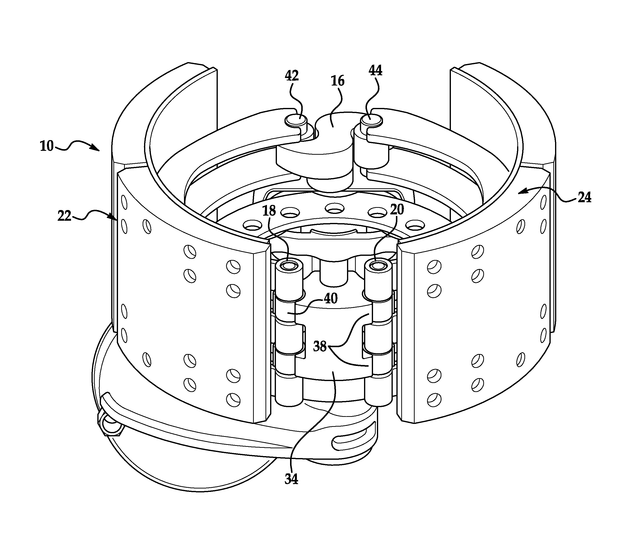
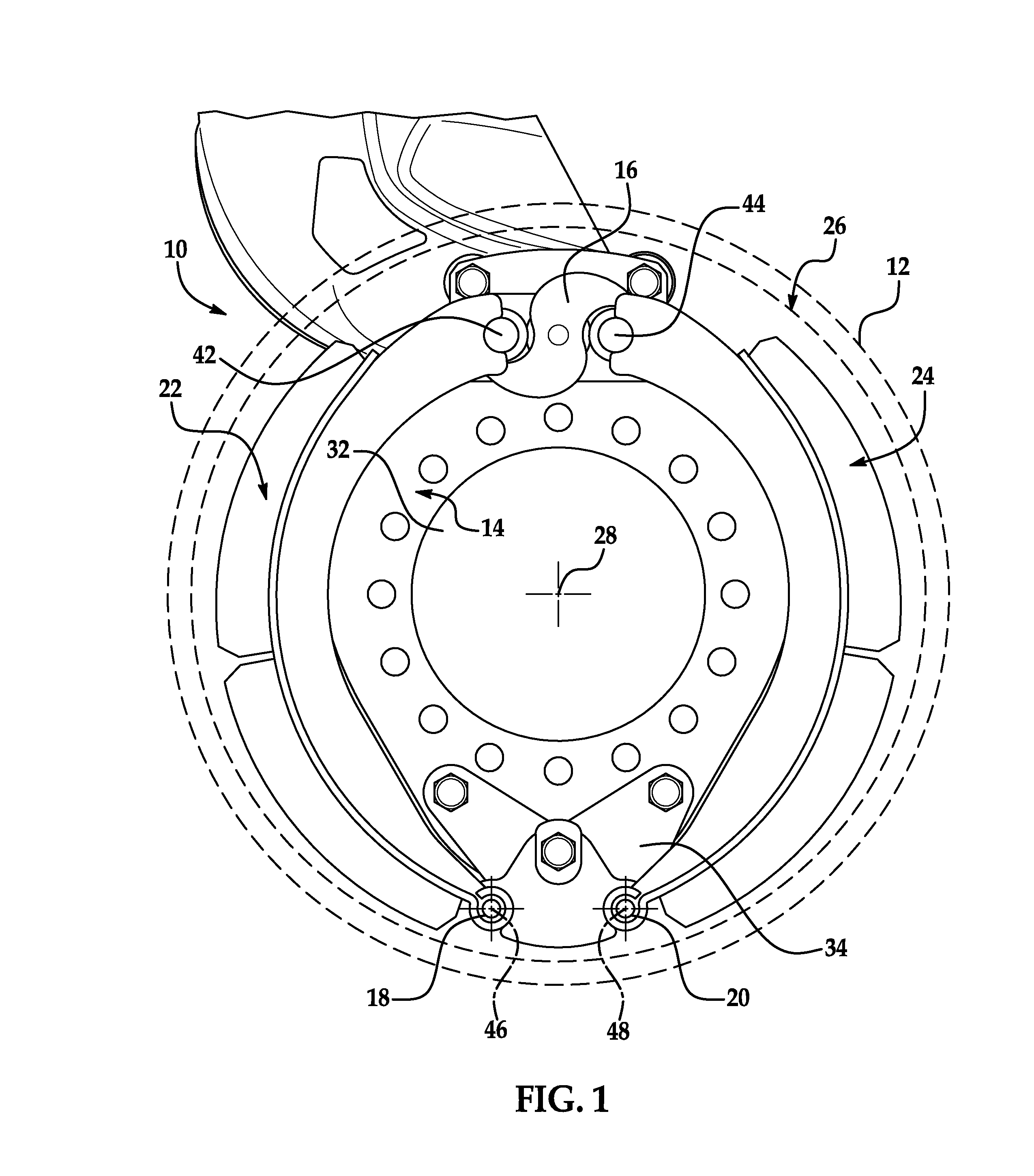
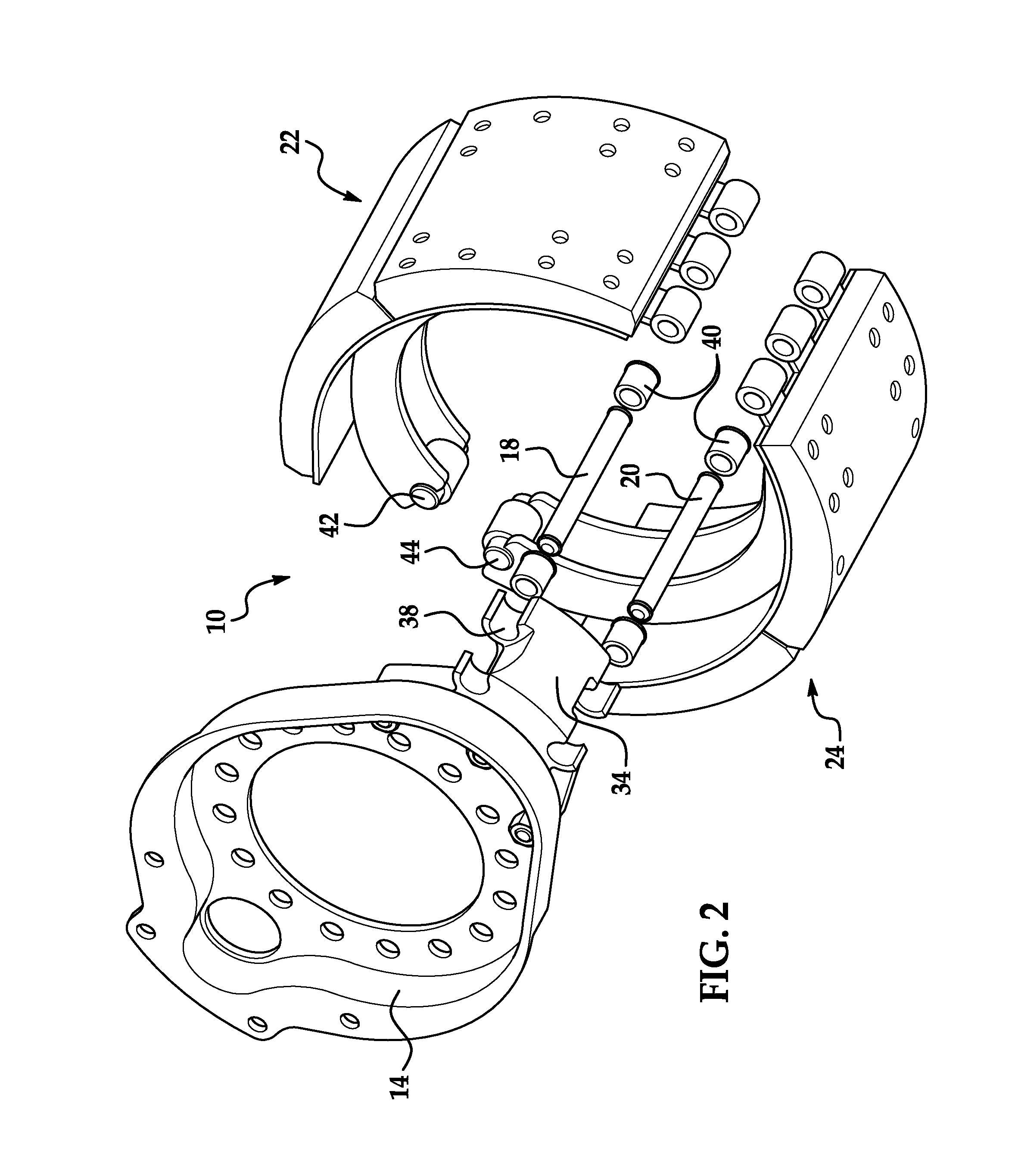
[0017]Referring now to the drawings wherein like reference numerals are used to identify identical components in the various views, FIGS. 1-4 illustrate a brake assembly 10 in accordance with one embodiment of the present invention. Brake assembly 10 is particularly adapted for use in heavy trucks. It should be understood, however, that brake assembly 10 may be used on a wide variety of vehicles and in non-vehicular applications. Brake assembly 10 is configured to act against a brake drum 12 (shown by phantom lines) and may include a brake spider 14, an actuating member 16, anchor pins 18, 20 and a pair of brake shoes 22, 24. Brake assembly 10 may also include other conventional components not discussed in detail herein including, for example, mounting brackets and hardware and an adjuster.

[0018]Brake drum 12 provides a braking surface 26 and is conventional in the art. Drum 12 may be made from conventional metals and metal alloys such as steel or cast iron. Drum 12 is annular and r...


PUM


Abstract

A brake shoe for a drum brake is provided. The brake shoe includes an arcuate brake table defining a radially outer side configured to receive a brake lining and a radially inner side opposite the radially outer side. The brake table further defines a plurality of sleeves proximate a first end of the brake table. The sleeves are aligned along an axis and axially spaced from one another. Each of the sleeves is configured to receive an anchor pin therein through which the brake shoe may be pivotally coupled to a brake spider. The sleeves are disposed about more than half of a perimeter of the anchor pin.

Description

BACKGROUND OF THE INVENTION[0001]a. Field of the Invention[0002]This invention relates to a drum brake. In particular, the invention relates to an improved brake shoe for a drum brake that enables more consistent brake dynamics, control and performance as compared to conventional brakes.[0003]b. Background Art[0004]In a conventional drum brake, a brake drum rotates with a wheel or wheels proximate to one end of an axle. The drum defines a radially inner braking surface. A brake spider is disposed about the axle and a pair of brake shoes are pivotally mounted at one end to the brake spider. The opposite end of each brake shoe is engaged by an actuating member such as a cam or hydraulic piston or wedge to move the brake shoes between positions of engagement and disengagement with the braking surface of the brake drum.[0005]Although drum brakes are generally less expensive than disc brakes, drum brakes may suffer from inconsistent brake dynamics, control and performance as compared to ...

Claims


Application Information

Patent Timeline
Patent Type & Authority Patents(United States)
IPC IPC(8): F16D65/08F16D51/20
CPCF16D65/08F16D51/20F16D65/09
Inventor PLANTAN, RONALD S.
Owner BENDIKS SPAJSER FAUNDEJSHN BREJK LLK
Why Eureka
Try Eureka