Light fixtures, lighting devices, and components for the same

a technology for lighting devices and light fixtures, which is applied in the direction of semiconductor devices for light sources, fixed installations, lighting and heating apparatus, etc. it can solve the problems of wasting significant amounts of light generated by the lamp, obtrusive and unattractive, and “eyeball” fixtures are often extremely inefficient, etc., and achieves easy change of type and/or pattern, easy removal and/or attachment, and reduction of skus

Active Publication Date: 2012-01-17
IDEAL IND LIGHTING LLC
View PDF16 Cites 99 Cited by
  • Summary
  • Abstract
  • Description
  • Claims
  • Application Information

AI Technical Summary

Benefits of technology

[0006]It would be desirable to provide light fixture accessories which can readily be removed and / or attached to light fixtures. Such devices would enable a user to easily change the type and / or pattern of light emitted from one or more light fixtures. In addition, such devices would result in an overall reduction on SKU numbers for a line of light fixtures, because each component could be assigned an SKU, rather than having to assign an SKU to each combination of light fixture and accessory.
[0007]In addition, it would be desirable to improve the performance of various light fixture accessories. For example, in the case of eyeball fixture accessories, it would be desirable to provide a product which is less obtrusive into the room space, for which kick angles (and aimability) can be more effectively controlled, and / or which result in improved energy efficiency (e.g., by blocking less light emitted by the light emitter attached to the light fixture).
[0143]The present inventive subject matter thus provides devices which allow the manufacturer's SKU count to stay low by “retrofitting” any standard recessed downlight into an eyeball fixture after initial installation. This same flexibility also allows for faster installation (by not requiring the contractor to differentiate between fixture types as he is installing) and increased consumer flexibility (by allowing the homeowner or user to move the “eyeball” accessories to whichever fixtures they deem appropriate, rather than having fixed installations.) Additionally, the accessory provides a method to “hide” some or all of its structure in the recess between the ceiling plane and the downlight diffuser, making it less obtrusive and more attractive. Furthermore, by using integral “kicker” reflectors made from highly reflective anodized aluminum (or metallized aluminum, or steel, or plastic with a vacuum metallized finish), and incorporating a purpose-designed diffusing, diffractive or Fresnel lens, the eyeball accessory wastes less light, giving a lower penalty to fixture efficacy than would otherwise be incurred by a traditional solution. Lastly, the devices according to the present inventive subject matter provide the ability to add different aesthetic treatments to a base white fixture, without the expense and difficulty of having to provide several to dozens of different finishes and textures on the fixture itself. Different optical profiles, finishes, and textures can be created in a trim accessory which snaps into the base fixture in a similar way (and using the same diffuser structure) as the eyeball accessory.

Problems solved by technology

Second, the “eyeball”, a hemispherical protrusion from the ceiling plane with an opening to direct light, typically extends into the room area to a significant degree, which can be considered by some people to be obtrusive and unattractive.
And third, especially in compact fluorescent fixtures, the “eyeball” fixture is often extremely inefficient, wasting significant amounts of the light generated by the lamp.

Method used


Image

  • Light fixtures, lighting devices, and components for the same
  • Light fixtures, lighting devices, and components for the same
  • Light fixtures, lighting devices, and components for the same

Examples


first embodiment

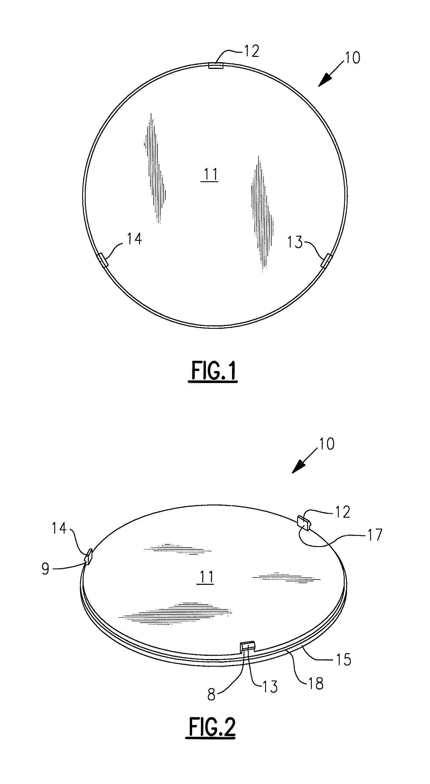
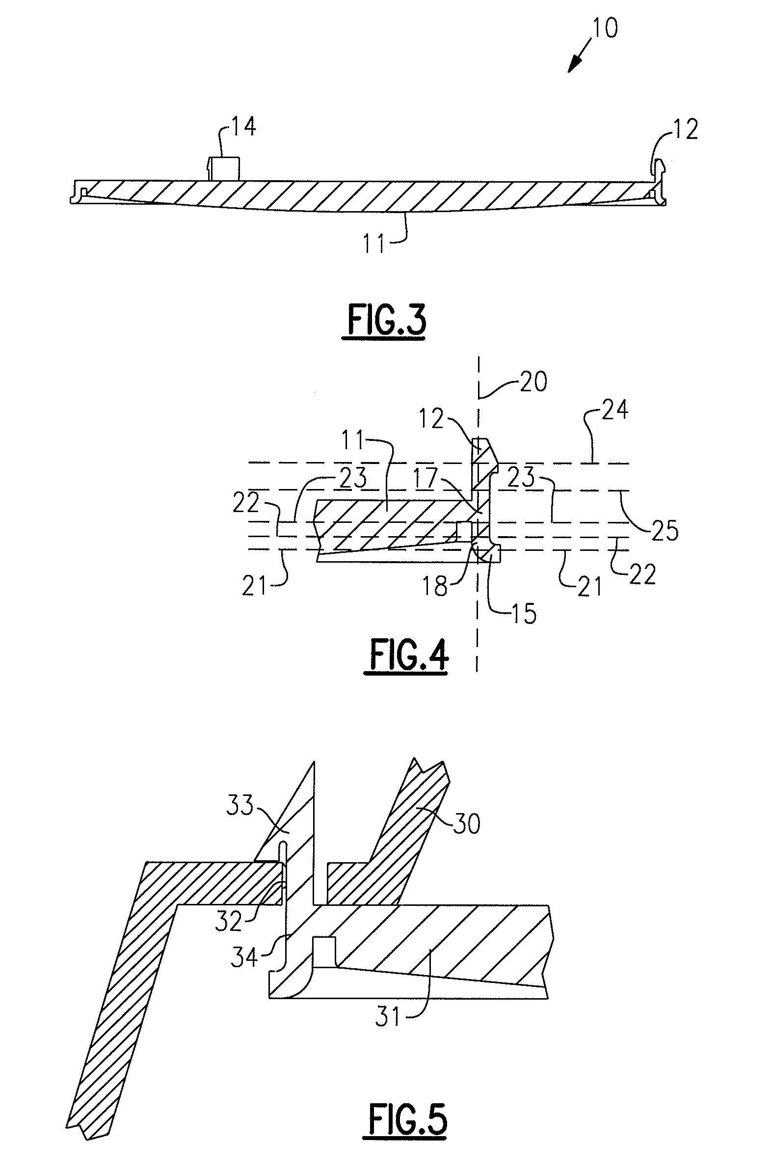
[0203]FIGS. 1-4 depict a diffuser for a lighting device according to the present inventive subject matter. FIG. 1 is a top view of the diffuser, FIG. 2 is a perspective view of the diffuser, FIG. 3 is a sectional view of the diffuser, and FIG. 4 is a partial view of the view shown in FIG. 3.

[0204]Referring to FIGS. 2 and 3, the diffuser 10 comprises a diffuser region 11, a first nose element 12, a second nose element 13, a third nose element 14, a first connection region 17 (extending from the diffuser region 11 to the first nose element 12), a circumferential hook element 15, a second connection region 18 (extending circumferentially from the diffuser region 11 to the hook element 15), as well as additional connection regions 8, 9 extending from the diffuser region 11 to the second nose element 13 and the third nose element 14, respectively.

[0205]Referring to FIG. 4, the first nose element 12 extends from a first connection region 17. As can be seen in FIG. 4, the widest part of th...

second embodiment

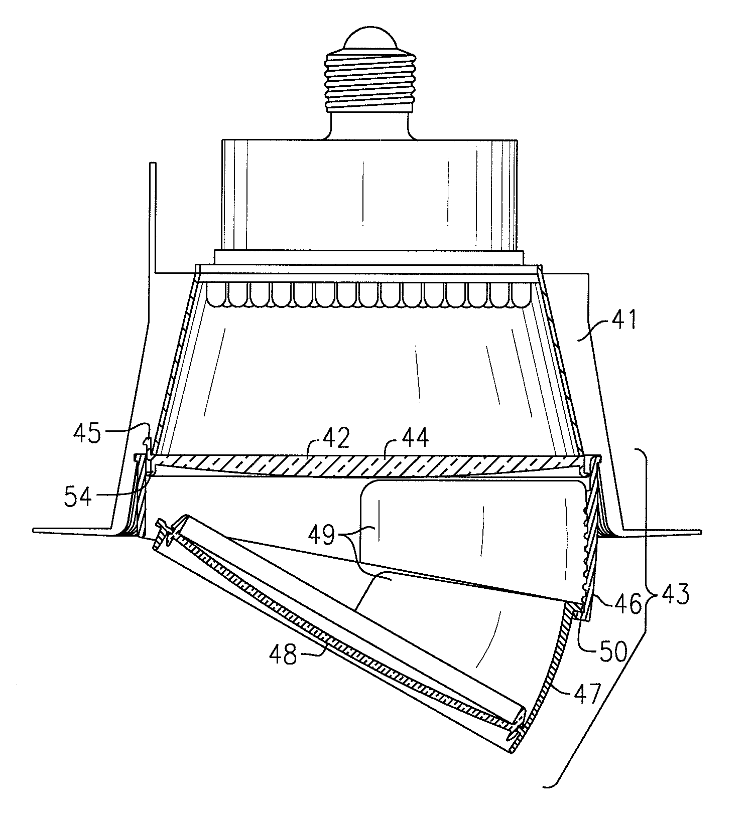
[0212]FIG. 6 depicts a light fixture according to the present inventive subject matter. The embodiment depicted in FIG. 6 comprises a light engine housing 41, a diffuser 42 and an accessory 43 (in this instance, an eyeball accessory). The diffuser comprises a diffuser region 44, a first nose element 45, a second nose element (not visible in FIG. 6), a third nose element (not visible in FIG. 6) and a circumferential hook element 54. The respective connection regions for the nose elements extend through openings in the light engine housing 41, thereby securing the nose elements in place. The hook element 54 engages spring elements which are biased inward from a peripheral edge of the accessory 43 in a manner as in the embodiment depicted in FIG. 10 and discussed below. In its most recessed configuration, the eyeball itself only protrudes approximately 1″ below the ceiling plane. The accessory 43 includes an upper eyeball housing 46, a lower eyeball housing 47, an eyeball diffuser 48, ...

third embodiment

[0213]FIG. 7 depicts a light fixture according to the present inventive subject matter. The embodiment depicted in FIG. 7 comprises a light engine housing 51, an attachment element 55 and an accessory 53 (in this instance, an eyeball accessory which includes a diffuser 56). The attachment element 55 comprises a first nose element 52, a second nose element (not visible in FIG. 7), a third nose element (not visible in FIG. 7) and a hook element 57. The nose elements extend through respective openings in the light engine housing, thereby securing the nose elements in place. The hook element 57 engages spring elements which are biased inward from a peripheral edge of the accessory 53 in a manner as in the embodiment depicted in FIG. 10 and discussed below. The embodiment depicted in FIG. 7 differs from the embodiment depicted in FIG. 6 in that the embodiment depicted in FIG. 7 does not include a diffuser in the light engine housing.


PUM


Abstract

A diffuser for a lighting device comprises a diffuser region, a hook element and a nose element. A light fixture comprises a housing with an opening and a diffuser as described above, in which the nose element extends through the opening, optionally further comprising an accessory including at least one spring element engaging the hook element. A light fixture structure comprises a housing defining an opening and an first attachment element comprising a nose element, a hook element and a connection region, and optionally further comprising a diffuser engaging a first portion of the hook element, and / or an accessory which engages a second portion of the hook element. An eyeball accessory comprises first and second housing elements pivotably attached to each other. An accessory for a light fixture comprises a housing member and a spring element engageable with a fixture.

Description

CROSS-REFERENCE TO RELATED APPLICATIONS[0001]This application claims the benefit of U.S. Provisional Patent Application No. 60 / 861,901, filed Nov. 30, 2006, the entirety of which is incorporated herein by reference.[0002]This application also claims the benefit of U.S. Provisional Patent Application No. 60 / 916,384, filed May 7, 2007, the entirety of which is incorporated herein by reference.FIELD OF THE INVENTION(S)[0003]The present inventive subject matter relates to light fixtures, lighting devices and components for light fixtures and lighting devices. In some aspects, the present inventive subject matter relates to removable and replaceable accessories for light fixtures.BACKGROUND OF THE INVENTION(S)[0004]There exist a number of different types of light fixture accessories. One example of a light fixture accessory is an “eyeball” fixture, i.e., a downlight with the capability to “push” light preferentially off axis (typically toward a wall or other structure).[0005]Traditional ...

Claims


Application Information

Patent Timeline
Patent Type & Authority Patents(United States)
IPC IPC(8): F21S8/02
CPCF21S8/02F21V3/00F21V17/02F21V17/164F21V17/007F21Y2101/02F21Y2101/00F21Y2115/10
Inventor TROTT, GARY DAVIDPICKARD, PAUL KENNETHADAMS, EDWARD ROGERVAN DE VEN, ANTONY PAUL
Owner IDEAL IND LIGHTING LLC
Why Eureka
Try Eureka