
Bussed haptic actuator system and method

a haptic actuator and actuator technology, applied in the field of haptic actuators, to achieve the effect of reducing pin count, avoiding or solving address conflicts, and improving user safety

Active Publication Date: 2015-08-13
MIDE TECH
View PDF14 Cites 108 Cited by
  • Summary
  • Abstract
  • Description
  • Claims
  • Application Information

AI Technical Summary

Benefits of technology

The patent text describes a better way of using bus devices, such as ICs, to improve user safety, reduce costs, and improve efficiency. The approach is to allow the address of each device to be configured in a way that avoids address conflicts and utilizes the entire address space to avoid or resolve address conflicts. The text also discusses how eliminating address select pins reduces the number of such devices and the overhead of setting a unique address for each device. Additionally, the patent describes how allowing the address of each device to be configured in such a way as to utilize the entire address space improves efficiency and reduces the amount of bus traffic needed to fully specify a multiactuator haptic pattern. The patent also describes how optional address grouping features allow more actuators to be controlled or controlled more quickly on the same bus, and optional address conflict resolution features reduce assembly costs by allowing serialized devices to be connected to the same bus arbitrarily without regard for possible address duplication on the bus. Finally, the patent describes a displacement limiter that reduces strain on the piezoelectric actuator and limits its displacement, providing a uniform peak displacement output for a broader range of frequencies near resonance.

Problems solved by technology

This is suboptimal due to the low number of selectable addresses relative to the total address space (limiting the number of such devices that can be used on a single bus), the need for extra pins and their associated electrical connections, and the overhead of setting a unique address for each device via pin configuration.

Method used


Image

  • Bussed haptic actuator system and method
  • Bussed haptic actuator system and method
  • Bussed haptic actuator system and method

Examples


Embodiment Construction

[0068]Aside from the preferred embodiment or embodiments disclosed below, this invention is capable of other embodiments and of being practiced or being carried out in various ways. Thus, it is to be understood that the invention is not limited in its application to the details of construction and the arrangements of components set forth in the following description or illustrated in the drawings. If only one embodiment is described herein, the claims hereof are not to be limited to that embodiment. Moreover, the claims hereof are not to be read restrictively unless there is clear and convincing evidence manifesting a certain exclusion, restriction, or disclaimer.

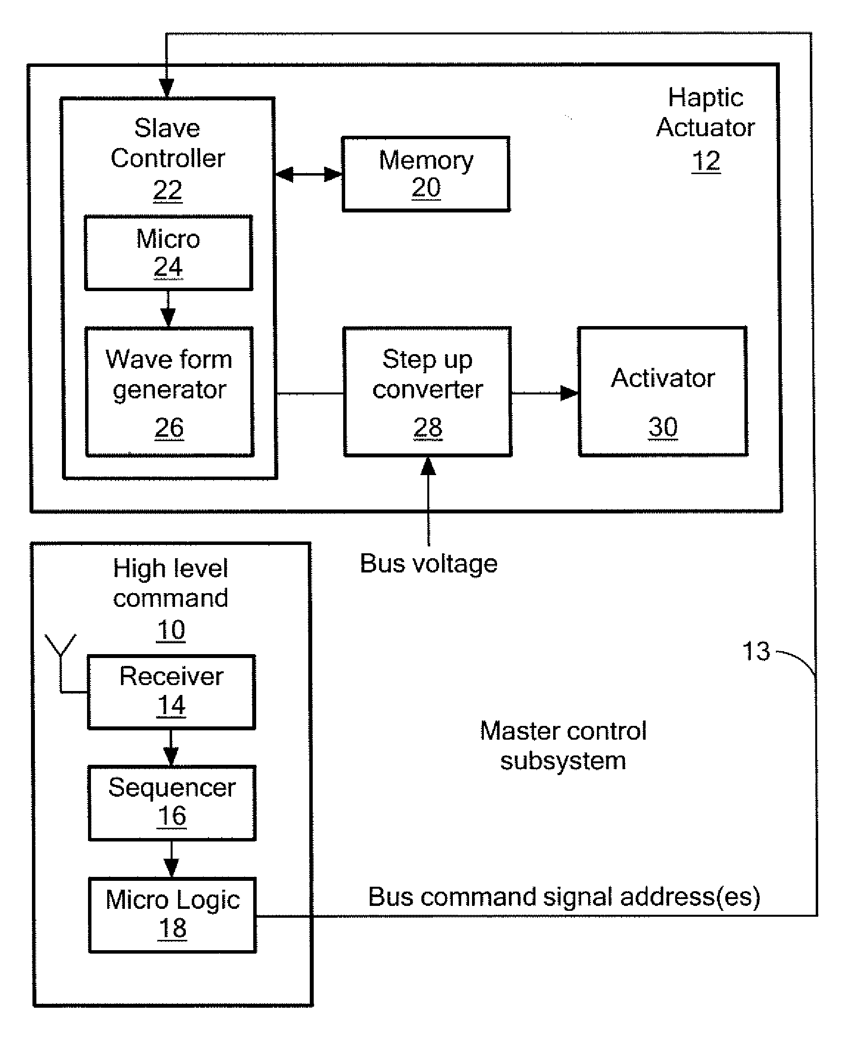
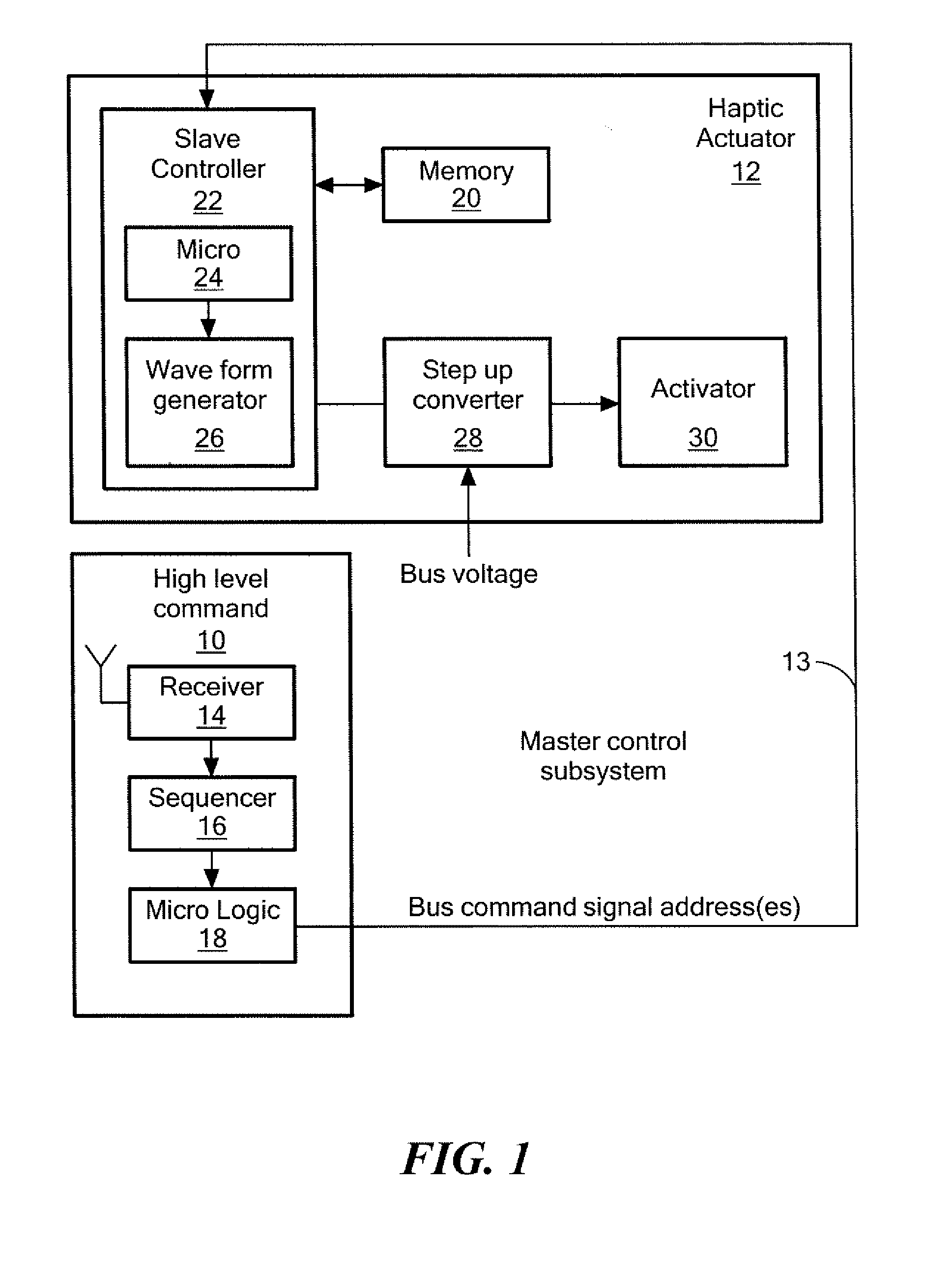
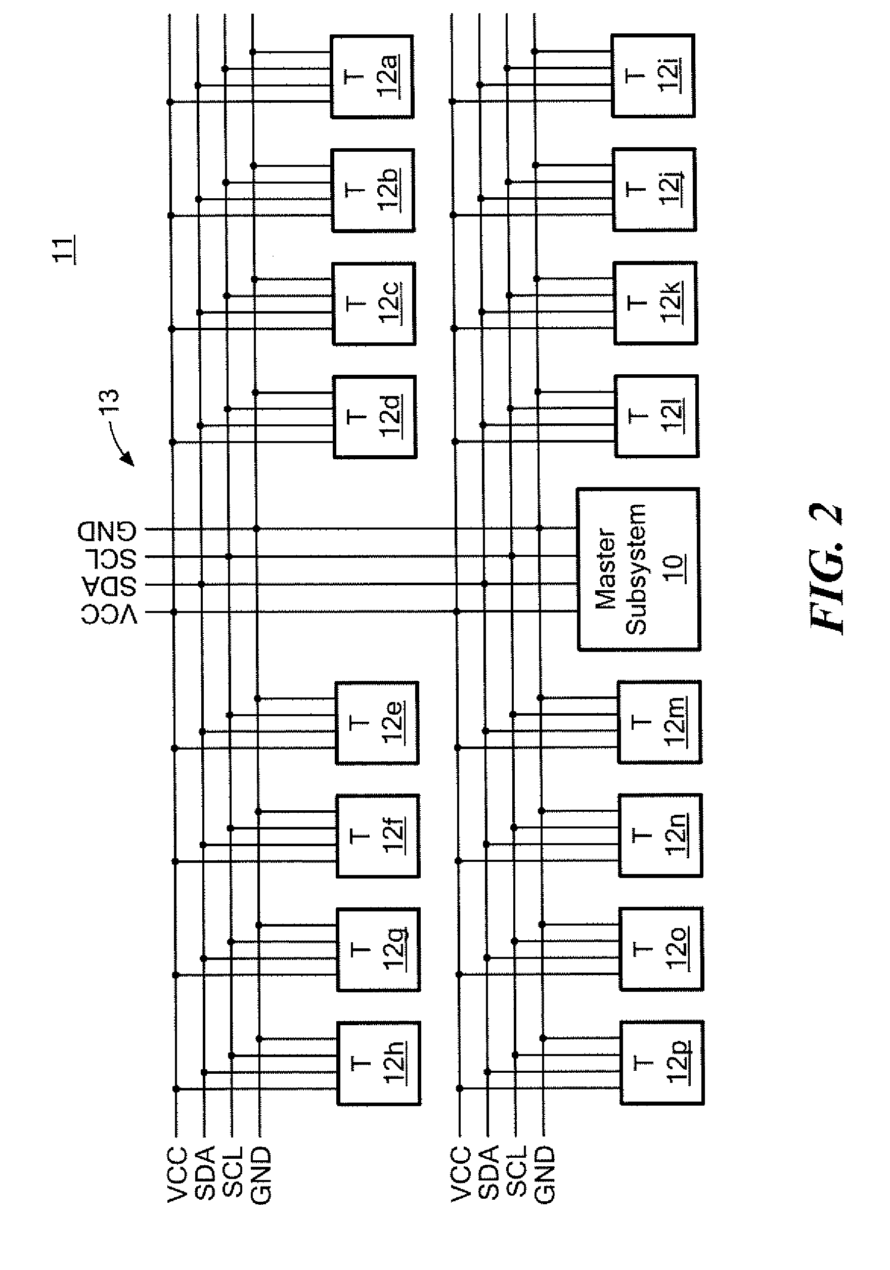
[0069]In one example, master control subsystem 10, FIG. 1 is connected to a plurality of haptic actuators such as haptic actuator 12 via a bus 13 architecture (e.g., IC2, SPI) as shown in FIG. 1. The bussed haptic actuator system 11, FIG. 2 may be incorporated, for example, in a product (e.g., a portable electronic device s...


PUM


Abstract

A bussed haptic actuator system includes a plurality of haptic actuators and a master control subsystem. Each haptic actuator includes a memory with an address storable therein and a slave controller subsystem configured to control the actuator in response to a received command signal. The master control subsystem is connected via a bus to the plurality of haptic actuators. The master control subsystem includes sequencer configured to determine which of the plurality of haptic actuators are to be activated and logic configured to provide, on the bus, a command signal including one or more addresses corresponding to haptic actuators to be activated as determined by the sequencer.

Description

RELATED APPLICATIONS[0001]This application claims benefit of and priority to U.S. Provisional Application Ser. Nos. 61 / 939,328 filed Feb. 13, 2014 and 61 / 939,331 filed Feb. 13, 2014 under 35 U.S.C. §§119, 120, 363, 365, and 37 C.F.R. §1.55 and §1.78 both of which are incorporated herein by reference.FIELD OF THE INVENTION[0002]This invention relates to haptic actuators.BACKGROUND OF THE INVENTION[0003]Haptic actuators provide tactile feedback to the user / wearer. In one example, a tactile actuator or “tactor” vibrates a piezoelectric beam to touch the wearer's body. It is hoped that haptic actuators may soon be used to remotely signal and / or command personnel such as military personnel in the field.[0004]Haptic display systems incorporating multiple actuators in an array (vest, garment, seatback, or distributed throughout a handheld device, etc.) driven in a controlled sequence via one or more serially-connected (shift-register-like) elements, referred to as MUXes, for demultiplexing...

Claims


Application Information

Patent Timeline
Patent Type & Authority Applications(United States)
IPC IPC(8): G06F3/01
CPCG06F3/016G06F1/3206G06F1/3287Y02D10/00
Inventor GIPSON, TIMOTHY R.HANLY, STEPHENKEEGAN, NOEL JARED
Owner MIDE TECH
Learn More